
A protection method for a pressurized water reactor overtemperature protection system of a nuclear power unit

A technology for nuclear power units and thermal protection, which is applied in mechanical equipment, engine components, machines/engines, etc., and can solve the problems of energy mismatch, decrease, and threats to the safety of nuclear power unit reactors.

Active Publication Date: 2021-06-15
ELECTRIC POWER RES INST OF GUANGXI POWER GRID CO LTD
View PDF0 Cites 0 Cited by
  • Summary
  • Abstract
  • Description
  • Claims
  • Application Information

AI Technical Summary

Problems solved by technology

[0002] It is unavoidable that the power grid fails or the nuclear power unit is abnormal. When the nuclear power unit cut-off protection action or load shedding operation with factory power, the steam turbine valve suddenly closes down, resulting in a sharp decrease in the steam intake of the steam turbine. The secondary circuit flows through The working medium of the steam generator will be reduced correspondingly, and the steam generator will not be able to take away the heat in the reactor, which will lead to overheating of the reactor and steam generator, and in severe cases, equipment damage and nuclear leakage accidents will occur
[0003] The nuclear power plant pressurized water reactor controls the reactivity through the control rod and the adjustment of the boron concentration. The adjustment of the boron concentration is a slow process. Considering the change of the reactivity caused by the reactant poison and the characteristics of the control rod itself, the rapid movement of the control rod also has certain restrictions. , so when the thermal power of the primary circuit and the electrical power of the secondary circuit do not match in energy, and there is a large deviation in the nuclear power unit, it will pose a threat to the safety of the nuclear power unit reactor

Method used


Image

  • A protection method for a pressurized water reactor overtemperature protection system of a nuclear power unit

Examples


Embodiment Construction

[0024] In order to better understand the present invention, the present invention will be further described below in conjunction with accompanying drawing and specific embodiment:

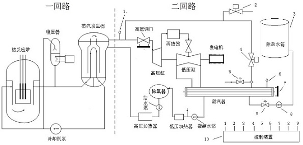
[0025] The nuclear power unit includes a primary circuit and a secondary circuit. The primary circuit includes a nuclear reactor, a voltage stabilizer, a steam generator, and a coolant pump; the secondary circuit includes a high-pressure valve, a reheater, a high-pressure cylinder, a low-pressure cylinder, a generator, a condenser, and a condenser. Water pumps, low-pressure heaters, deaerators, feed water pumps, high-pressure heaters, the connection relationship between the primary circuit and the secondary circuit is as follows figure 1 As shown, this part is the prior art, and will not be repeated here.

[0026] Such as figure 1 As shown, a pressurized water reactor overtemperature protection system for a nuclear power unit includes a secondary circuit main steam pressure measuring device 1, an ...


PUM


Abstract

The invention relates to the technical field of nuclear power unit stability control, in particular to a nuclear power unit pressurized water reactor over-temperature protection system and a protection method thereof. Valve, bypass desuperheater, condenser vacuum measuring device, condenser water level gauge, desalted water delivery pump, desalted water delivery regulating valve, control device; control device collects secondary circuit main steam pressure measuring device, condenser vacuum The measurement results of the measuring device and the water level gauge of the condenser control the working status of the air exhaust valve, bypass valve, bypass desuperheater, desalinated water delivery pump, and desalted water delivery regulating valve, so as to realize the monitoring of the reactor and steam generator. Over-temperature protection, and real-time replenishment of the secondary circuit working medium to prevent damage to the condenser, in which the bypass desuperheater can spray water to reduce the temperature of the high-temperature steam before entering the condenser, which can prevent high temperature from affecting the condenser damage.

Description

technical field [0001] The invention relates to the technical field of nuclear power unit stability control, in particular to a protection method for a pressurized water reactor overtemperature protection system of a nuclear power unit. Background technique [0002] It is unavoidable that the power grid fails or the nuclear power unit is abnormal. When the nuclear power unit cut-off protection action or load shedding operation with factory power, the steam turbine valve suddenly closes down, resulting in a sharp decrease in the steam intake of the steam turbine. The secondary circuit flows through The working medium of the steam generator will be reduced correspondingly, and the steam generator cannot take away the heat in the reactor, which will cause the reactor and steam generator to overheat, and in severe cases, it will cause equipment damage and nuclear leakage accidents. [0003] The nuclear power plant pressurized water reactor controls the reactivity through the con...

Claims


Application Information

Patent Timeline
Patent Type & Authority Patents(China)
IPC IPC(8): F01D17/14F01D25/12F01D25/00F01D21/00F01D21/14
CPCF01D17/145F01D21/003F01D21/14F01D25/00F01D25/12
Inventor 文立斌刘光时吴健旭雷亭
Owner ELECTRIC POWER RES INST OF GUANGXI POWER GRID CO LTD
Learn More