Eureka AIR delivers breakthrough ideas for toughest innovation challenges, trusted by R&D personnel around the world.

Ignition device for micro turbojet engine and gas turbine combustor

A turbojet engine and gas turbine technology, applied in the direction of gas turbine devices, jet propulsion devices, machines/engines, etc., can solve the problems of immature aerodynamic resonance technology, ignition system cost and increase in volume and weight, and achieve faster flame diffusion speed, The effect of simple and reliable structure and low cost

Active Publication Date: 2020-12-01
北京领动国创科技有限公司
View PDF10 Cites 0 Cited by
  • Summary
  • Abstract
  • Description
  • Claims
  • Application Information

AI Technical Summary

Problems solved by technology

The main disadvantage of this ignition method: on the one hand, the aerodynamic resonance technology is still in the exploratory stage and is not very mature
On the other hand, pneumatic resonance requires compressed gas as the working medium for generating heat, so an additional compressed gas tank is required, which greatly increases the cost and volume weight of the entire ignition system

Method used


Image

  • Ignition device for micro turbojet engine and gas turbine combustor
  • Ignition device for micro turbojet engine and gas turbine combustor
  • Ignition device for micro turbojet engine and gas turbine combustor

Examples


Embodiment Construction

[0033] The present invention will be described in further detail below in conjunction with the accompanying drawings.

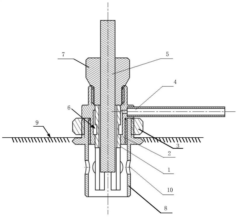
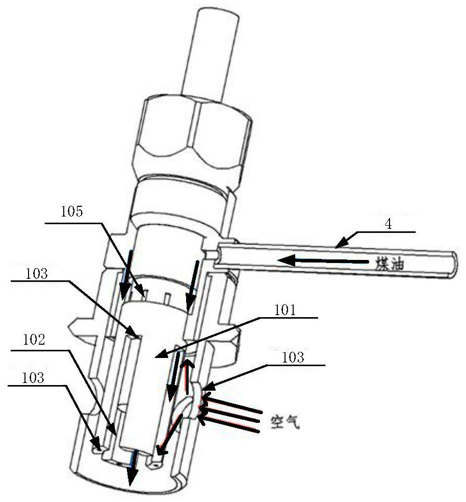
[0034] The ignition device for the miniature turbojet engine and gas turbine combustor of the present invention comprises a kerosene nozzle 1, a kerosene cavity seat 2, a fastening nut 3, an oil inlet pipe 4 and a heating core 5, such as figure 1 shown.

[0035] The kerosene nozzle 1, the kerosene cavity seat 2, the oil inlet pipe 4 and the heating core 5 form an oil circuit assembly. Wherein, the heating core 5, the kerosene nozzle 1 and the kerosene cavity seat 2 are coaxially nested from inside to outside. The upper and lower parts of the kerosene chamber seat 2 are designed with contact shoulders, which are in contact with the top of the kerosene nozzle 1 and the outer wall of the middle part, and are welded and fixed in the circumferential direction to form an integrated weldment, so that the kerosene chamber seat 2 and the kerosene nozzle 1 form a Cav...


PUM


Abstract

The invention discloses an ignition device for a micro-miniature turbojet engine and gas turbine combustion chamber. The ignition device is composed of a kerosene nozzle, a kerosene chamber seat, a fastening nut, an oil inlet pipe and a heating core, the whole body is mounted on an engine shell through an air inlet cover, six air inlet holes are formed in the cylindrical surface of the air inlet cover, air can enter an ignition device combustion area through the air inlet holes to be mixed with the kerosene, the kerosene nozzle is provided with a pre-combustion hole and a main oil hole, the kerosene can be sprayed out through the pre-combustion hole and the main oil hole correspondingly so as to achieve layered combustion of the kerosene, the heating core adopts a silicon nitride ceramic electric heating plug, so that the power is large, the air enters the ignition area from the air inlet cover, the kerosene enters the kerosene chamber seat from the oil inlet pipe, and is sprayed out from the pre-combustion hole and the main oil hole in two paths through the kerosene nozzle. The oil discharge amount near the pre-combustion hole is relatively small, moreover, a pre-combustion area with a lower air flow speed is provided, the flame combusting stably existing in the pre-combustion area in the wide working condition range can help to ignite the kerosene sprayed out of the main oilhole, and then it is guaranteed that the igniter can work stably and reliably in the wider working condition range.

Description

technical field [0001] The invention belongs to the field of micro turbojet engines and gas turbines, and relates to a method for igniting a combustion chamber of a micro turbojet engine and a gas turbine and an ignition device for implementing the method, which can be applied to the ignition process of a micro turbojet engine and a gas combustion chamber of a gas turbine. Background technique [0002] Micro turbojet engines and gas turbines that use kerosene as aviation fuel are limited by size and structure. The structure of the combustion chamber and fuel nozzle is relatively simple. There is no special ignition and kerosene atomization device, so it is difficult to ensure that the engine starts The poor quality of kerosene atomization makes it difficult to start ignition and flame propagation. This is also the reason why many micro turbojet engines and gas turbines do not directly ignite kerosene but use propane gas to ignite. The propane gas injected into the combustion...

Claims


Application Information

Patent Timeline
Patent Type & Authority Patents(China)
IPC IPC(8): F02C7/264
CPCF02C7/264
Inventor 周煜姬芬竹张向波杜发荣吕展
Owner 北京领动国创科技有限公司
Why Eureka
Eureka Blog
Learn More