Detection device on turbocharger actuator assembly line
A technology of a turbocharger and a detection device, which is applied in the field of actuators, can solve the problems of large interference factors, large labor force, general applicability, etc., and achieves the effect of good applicability and convenient detection.
- Summary
- Abstract
- Description
- Claims
- Application Information
AI Technical Summary
Problems solved by technology
Method used
Image

Examples
Embodiment 1
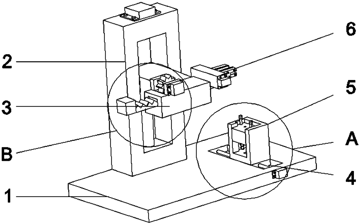
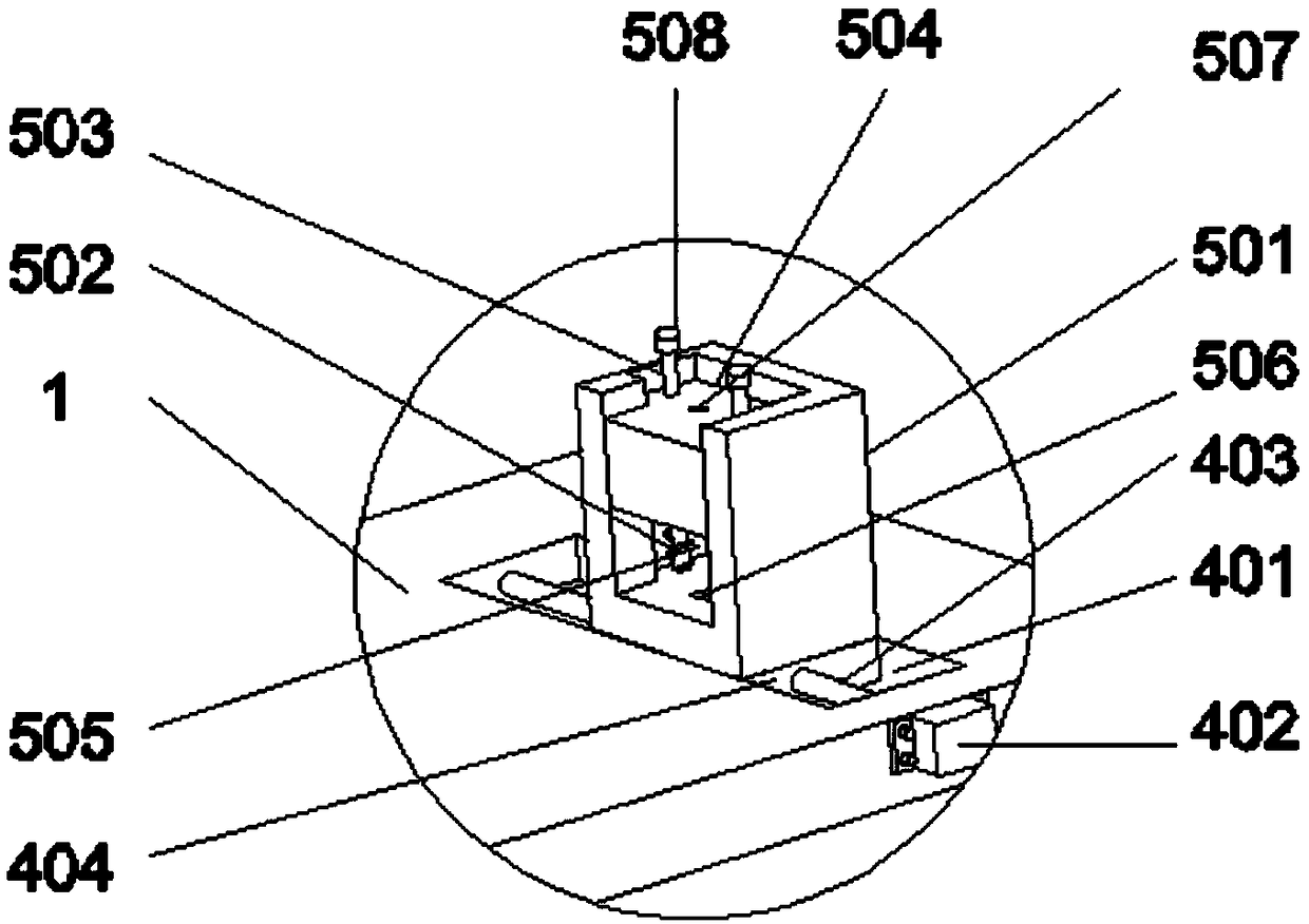
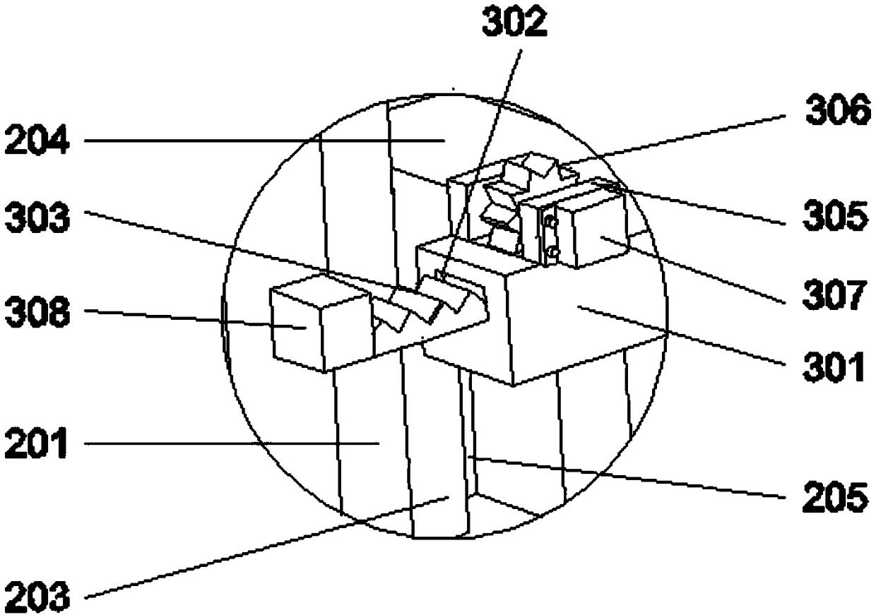
[0024] Such as Figure 1 to Figure 7As shown, a detection device on a turbocharger actuator assembly line includes a base 1, and the base 1 is provided with a lifting mechanism 2, and the lifting end of the lifting mechanism 2 is connected with a lateral sliding mechanism 3. The clamping mechanism 6 includes a clamping bracket 601, a clamping servo motor 602, a clamping threaded rod 603, a first clamping block 604, a second clamping block 605, and a clamping chute 606, and the clamping bracket 601 is connected to the lateral slide The sliding end of the shift mechanism 3, the clamping chute 606 is set on the clamping bracket 601 and is perpendicular to the transverse mechanism 3. The clamping threaded rod 603 is rotatably connected in the clamping chute 606, and the clamping servo The motor 602 is arranged on the clamping bracket 601, and the first clamping block 604 and the second clamping block 605 are arranged symmetrically on the clamping threaded rod 603 and are slidably ...
Embodiment 2
[0027] Such as Figure 1 to Figure 7 As shown, a detection device on a turbocharger actuator assembly line includes a base 1, and the base 1 is provided with a lifting mechanism 2, and the lifting end of the lifting mechanism 2 is connected with a lateral sliding mechanism 3. The clamping mechanism 6 includes a clamping bracket 601, a clamping servo motor 602, a clamping threaded rod 603, a first clamping block 604, a second clamping block 605, and a clamping chute 606, and the clamping bracket 601 is connected to the lateral slide The sliding end of the shift mechanism 3, the clamping chute 606 is set on the clamping bracket 601 and is perpendicular to the transverse mechanism 3. The clamping threaded rod 603 is rotatably connected in the clamping chute 606, and the clamping servo The motor 602 is arranged on the clamping bracket 601, and the first clamping block 604 and the second clamping block 605 are arranged symmetrically on the clamping threaded rod 603 and are slidably...
PUM
 Abstract
Description
Claims
Application Information
PatSnap Eureka turns technology decisions into work you can execute. Powered by our Innovation Knowledge Graph, it runs expert workflows across engineering, life sciences, materials and intellectual property. Get your review-ready output in minutes.


