
Color stereo moire imaging optical device

An imaging optics, color stereo technology, applied in optics, optical components, lenses, etc., can solve the problems of low imaging contrast and brightness, inability to adjust, affecting the viewing effect, etc., and achieve high contrast and wide range of applications.

Active Publication Date: 2019-03-08
SUZHOU UNIV
View PDF6 Cites 7 Cited by
  • Summary
  • Abstract
  • Description
  • Claims
  • Application Information

AI Technical Summary

Problems solved by technology

However, the limitations of the visual effects of this type of moiré imaging film are very obvious, mainly in: 1) the color is single, and only one color effect can be displayed; 2) the imaging contrast and brightness are not high, and cannot be adjusted; 3) Affected by ambient light, multiple moiré magnified images are formed, which affects the viewing effect

Method used


Image

  • Color stereo moire imaging optical device
  • Color stereo moire imaging optical device
  • Color stereo moire imaging optical device

Examples


Embodiment Construction

[0028] The present invention will be further described below in conjunction with the accompanying drawings and specific embodiments, so that those skilled in the art can better understand the present invention and implement it, but the examples given are not intended to limit the present invention.

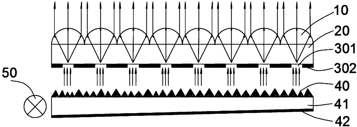
[0029] refer to Figure 1-Figure 6 As shown, the present invention discloses a color stereo moiré imaging optical device, which includes a micro-pattern layer 30 , a backlight module and a micro-focusing layer 10 .

[0030] The micro-text layer 30 includes transparent micro-text units 301 arranged in an array, and an opaque background layer 302 is arranged between the transparent micro-text units 301 and the transparent micro-text units 301 . The backlight module is located on one side of the micro-texture layer 30 , and the backlight module provides uniform illumination for the micro-texture layer 30 . The micro-focus layer 10 is located on the other side of the micro-texture la...


PUM


Abstract

The invention discloses a color stereo moire imaging optical device. The device comprises a micro-text layer, the micro-text layer comprises transparent micro-text units arranged in an array, and an opaque background layer is between the transparent micro-text units; a backlight module is disposed on one side of the micro-text layer, and the backlight module provides uniform illumination for the micro-text layer; a micro-focus layer is located on the other side of the micro-text layer, the micro-focusing layer comprises a micro-focusing unit arranged in an array, and a spacer layer is arrangedbetween the micro-focusing layer and the micro-text layer; stereoscopic, colored and magnified micro-texts and micro-images can be observed by naked eyes through the micro-focusing layer. The devicecan form a color stereoscopic image, can be seen by the naked eyes, have a wide field of view, have a stereoscopic effect, and have application prospects in the fields of stereoscopic imaging and display.

Description

technical field [0001] The invention relates to the technical field of stereo imaging, in particular to a color stereo moiré imaging optical device. Background technique [0002] Three-dimensional imaging is the ultimate goal of display technology. Countries, enterprises and research institutions continue to invest a lot of financial and material resources in research. In recent years, thanks to massive R&D investment and progress in optoelectronic technology, various 3D imaging technologies have flourished, bringing people an unprecedented visual experience. [0003] Stereoscopic display technology is a display device that can watch 3D images with naked eyes. In this technology, a light control structure is generally required to control the direction of the light emitted by the two-dimensional display to form a spatial viewpoint, so that the left and right eyes can receive different disparity maps, and then the three-dimensional effect can be formed through brain fusion. ...

Claims


Application Information

Patent Timeline
Patent Type & Authority Applications(China)
IPC IPC(8): G02B3/00G02B3/08G02B27/22
CPCG02B3/0056G02B3/08G02B30/27
Inventor 申溯郑伟伟周云
Owner SUZHOU UNIV
Learn More