
High-precision high-voltage current source circuit

A high-voltage current source, high-precision technology, applied in the direction of regulating electrical variables, control/regulating systems, instruments, etc., can solve the problems of circuit operating point changes, low output current, poor stability, etc., to achieve convenient control, protection of load safety, The effect of ensuring reliability

Active Publication Date: 2019-03-08
HANGZHOU CHENGNUO MEDICAL SCI & TECH CO LTD
View PDF10 Cites 5 Cited by
  • Summary
  • Abstract
  • Description
  • Claims
  • Application Information

AI Technical Summary

Problems solved by technology

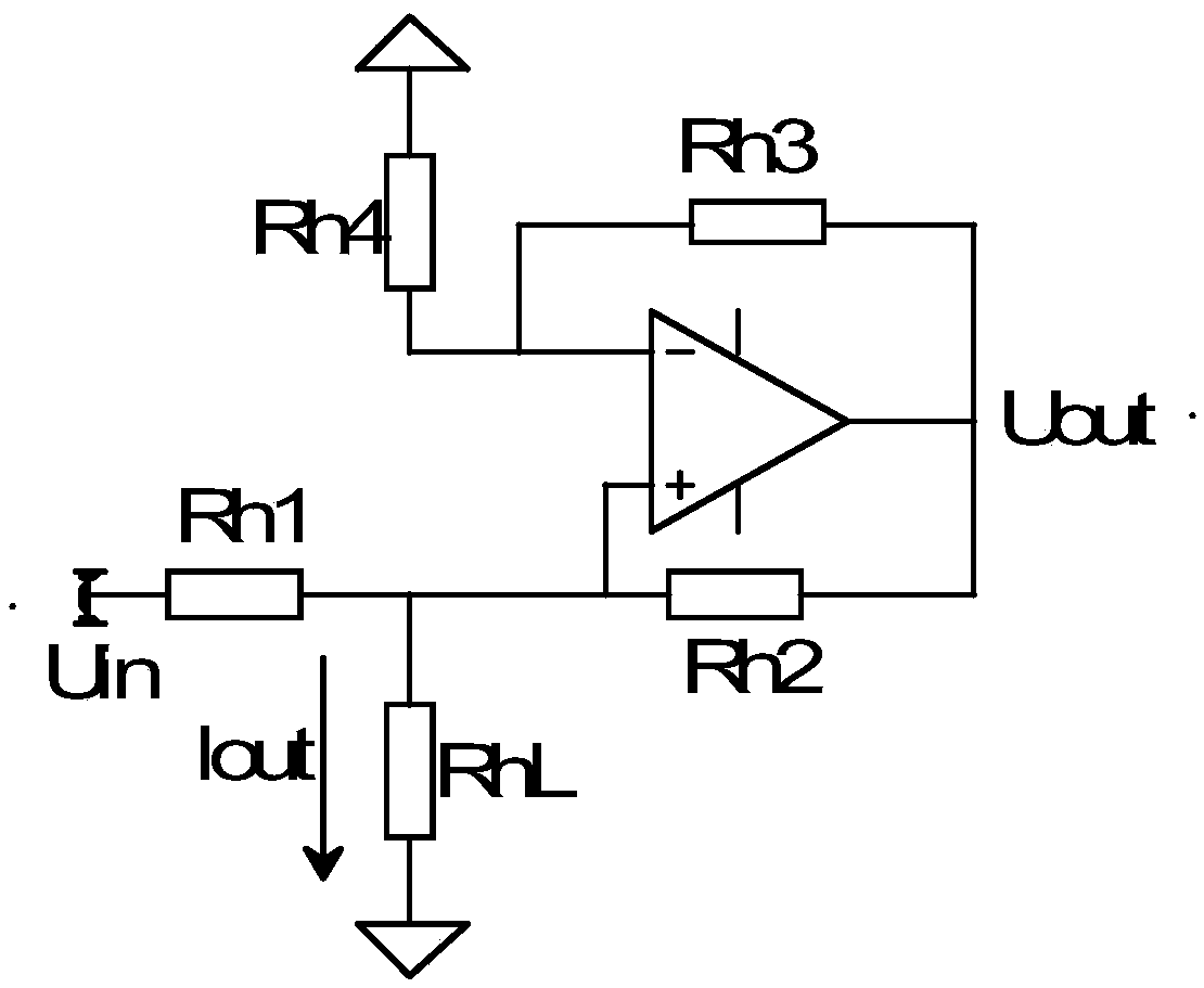
[0007] The main problem of the Howland current source is: poor stability. If the RhL terminal is removed, the op amp will enter a saturated state. At this time, the originally designed circuit function will not be realized. The output current is low, the efficiency is low, and the bias of the op amp itself is affected by Ibias. It is also very large, and it is difficult for the four matching resistors on the periphery to be exactly the same
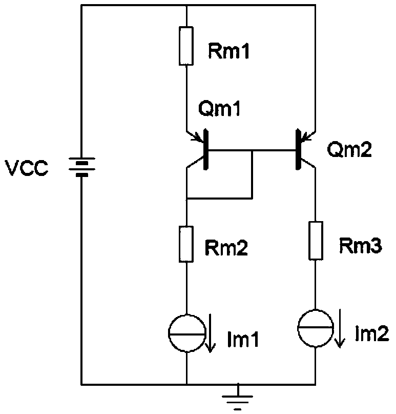
[0008] The current mirror current source depends on the Ib current of Qm1 on the left to maintain the stability of the Ib current of Qm2 on the right. When the base current Ib of the triode is constant, Rm3 is the load impedance. When the load resistance changes, such as increases, Rm3*Im2 becomes larger, the collector potential Uc of the Qm2 tube increases, and Uce=VCC-Uc of the Qm2 triode causes the potential between the Uce electrodes to decrease, which in turn leads to a change in the operating point of the circuit, resulting in a change in the Ic current, which in turn affects the constant current source circuit. output stability
At the same time, the temperature stability of the current mirror constant current source is poor, and the single-tube temperature rise of the Qm1 and Qm2 transistors can easily lead to distortion of the output characteristics

Method used


Image

  • High-precision high-voltage current source circuit
  • High-precision high-voltage current source circuit
  • High-precision high-voltage current source circuit

Examples


Embodiment Construction

[0042] In order to make the object, technical solution and advantages of the present invention clearer, the present invention will be further described in detail below in conjunction with the accompanying drawings and embodiments. It should be understood that the specific embodiments described here are only used to explain the present invention, not to limit the present invention.

[0043] On the contrary, the invention covers any alternatives, modifications, equivalent methods and schemes within the spirit and scope of the invention as defined by the claims. Further, in order to make the public have a better understanding of the present invention, some specific details are described in detail in the detailed description of the present invention below. The present invention can be fully understood by those skilled in the art without the description of these detailed parts.

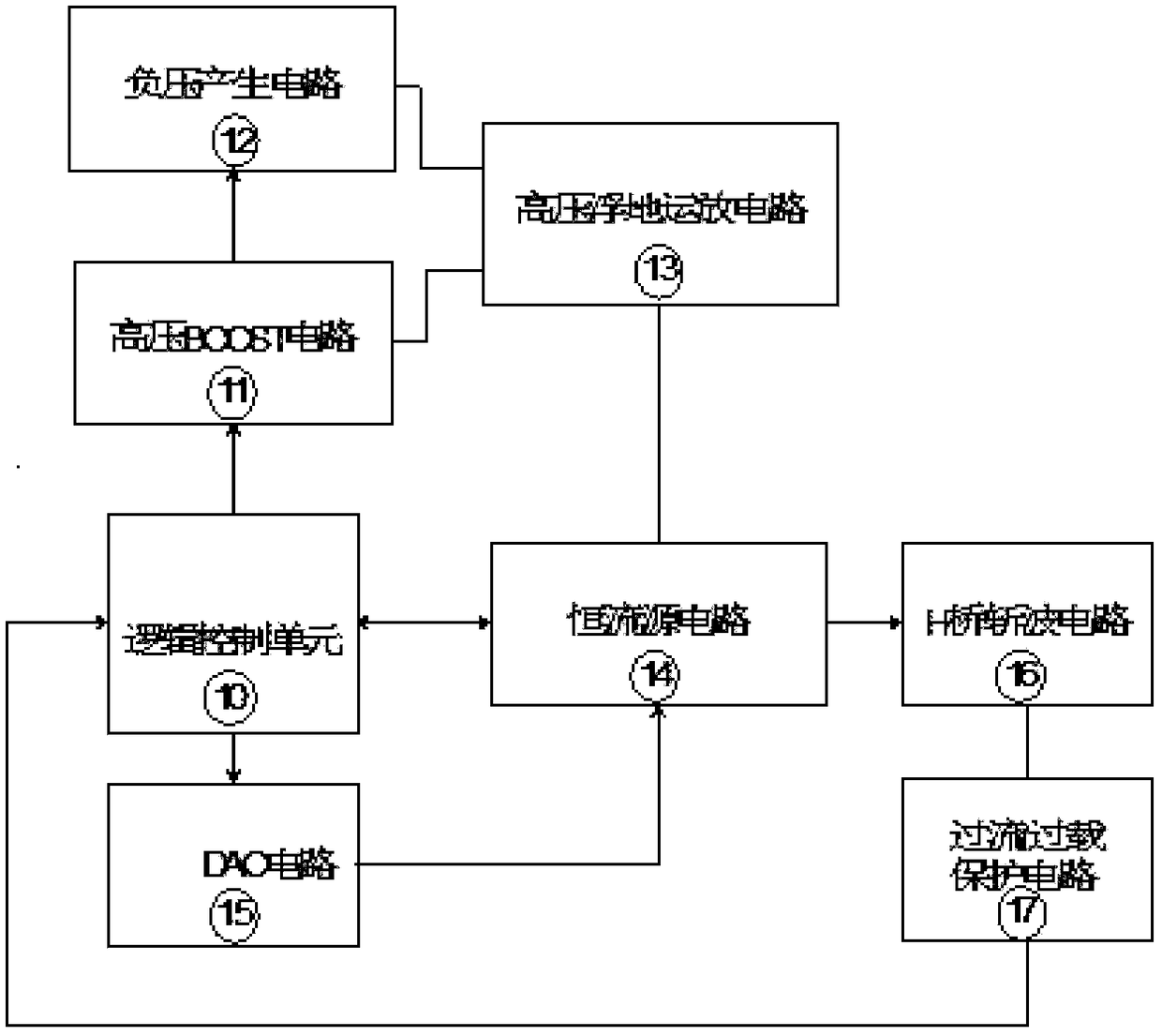
[0044] see image 3 , shows a structural block diagram of a high-precision high-voltage current sourc...


PUM


Abstract

The invention discloses a high-precision high-voltage current source circuit. The high-precision high-voltage current source circuit comprises a logic control unit, a high-voltage Boost circuit, a negative pressure generation circuit, a DAC circuit, a high-voltage floating operation and amplification circuit, a constant-current source circuit, a bridge-H chopper circuit, and an overcurrent overload protection circuit. By adopting the high-precision high-voltage current source circuit, the problems of the traditional Howland current source that the stability is poor, the circuit is easy in saturation state, the output current is relatively low, the efficiency is relatively low, the influence of the operation and amplification Ibias is great, the four peripheral matching resistors are difficult in consistency and the like can be solved. The high-precision high-voltage current source circuit is capable of realizing the fine stepper adjustment for the current, large in current output range, high in load capacity, flexible and variable in circuit parameters and relatively low in requirement for the consistence of peripheral parameters.

Description

technical field [0001] The invention belongs to the field of electronic circuits and relates to a high-precision high-voltage current source circuit. Background technique [0002] Current sources, a vast field. The most basic current source circuit is a simple current source or a current mirror current source composed of triodes, see figure 1 ; After the popularization and application of integrated operational amplifier circuits, a constant current source circuit composed of operational amplifier units combined with resistors, namely the Howland current source, appeared. figure 2 , the circuit model provides guidance for the follow-up constant current source circuit based on the op amp topology. [0003] In addition to adding negative feedback, the Howland current source also has a positive feedback link. In the Howland current source, Rh3 and Rh4 form a negative feedback network, and the output is fed back to the inverting input terminal. The feedback coefficient is Rh4 / ...

Claims


Application Information

Patent Timeline
IPC IPC(8): G05F1/46
CPCG05F1/461
Inventor 李浩余容英
Owner HANGZHOU CHENGNUO MEDICAL SCI & TECH CO LTD
Learn More