Optical module monitoring system and method

A monitoring system and optical module technology, applied in the field of communication, can solve problems such as difficult to realize optical module status monitoring, and achieve the effect of improving monitoring efficiency, simple communication logic, and efficient monitoring

Pending Publication Date: 2019-03-08
广州开信通讯系统有限公司
View PDF6 Cites 8 Cited by
  • Summary
  • Abstract
  • Description
  • Claims
  • Application Information

AI Technical Summary

Problems solved by technology

[0004] However, the host generally has limited I2C interfaces (2 to 3), and it is difficult to monitor the status of more optical modules in a scenario where there are too many optical modules

Method used


Image

  • Optical module monitoring system and method
  • Optical module monitoring system and method
  • Optical module monitoring system and method

Examples


Embodiment Construction

[0043] In order to make the purpose, technical solution and advantages of the present application clearer, the present application will be further described in detail below in conjunction with the accompanying drawings and embodiments. It should be understood that the specific embodiments described here are only used to explain the present application, and are not intended to limit the present application.

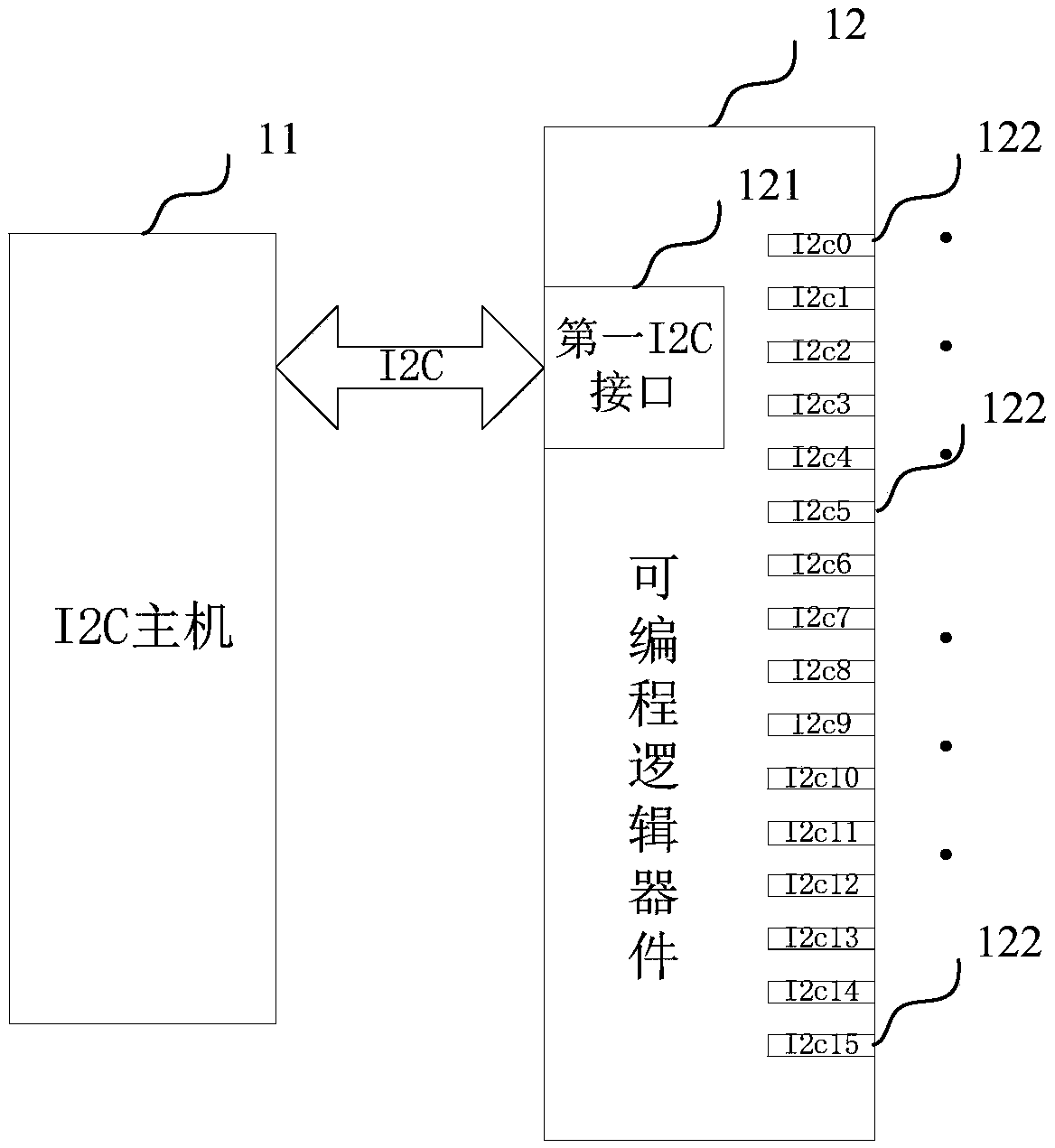
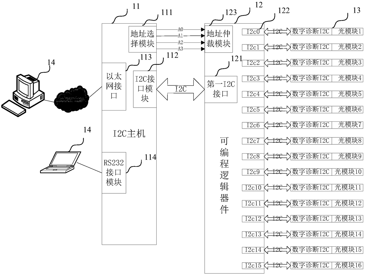
[0044] In one embodiment, such as figure 1As shown, an optical module monitoring system is provided, and the system may include: an I2C host 11, a programmable logic device 12, and the programmable logic device 11 may include a first I2C interface 121 and a plurality of second I2C interfaces 122, the I2C host 11 is based on the first I2C interface 121, and is connected to the programmable logic device 12 through a group of two-wire serial bus I2C bus, and a second I2C interface 122 can be connected through a group of I2C bus Connect an optical module; the I2C host 11 is u...


PUM


Abstract

The present application relates to an optical module monitoring system and method. The system comprises an I2C master and a programmable logic device, the programmable logic device includes a first I2C interface and a plurality of second I2C interfaces, the I2C master is based on the first I2C interface and is connected with the programmable logic device through a group of two-wire serial I2C buses, and a second I2C interface is connected with an optical module through a group of I2C buses. The I2C master is used for gating the target I2C interface corresponding to the first I2C interface andthe target optical module through the programmable logic device, a target address is written into the memory of the target optical module through the first I2C interface and the target I2C interface,and the status parameters stored in the target address returned by the target optical module are received. The system can realize the efficient monitoring of multiple optical modules through the simple communication logic scalability, and has the very high practicability.

Description

technical field [0001] The present application relates to the technical field of communications, and in particular to a system and method for monitoring an optical module. Background technique [0002] With the development of digital technology and optical fiber communication technology, digital optical modules are widely used in communication systems. Therefore, the monitoring requirements of the operating status of optical modules are put on the agenda, so as to facilitate on-site and remote analysis of optical communication faults and communication quality. With the release of the SFF Committee (Small Form Factor Committee) SFF-8472 protocol, many optical module manufacturers have launched optical modules that support this protocol, providing a technical basis for real-time monitoring of optical modules. [0003] SFF-8472 stipulates that all optical modules supporting this protocol use the I2C bus interface to communicate. In I2C interface communication, it is stipulated...

Claims


Application Information

Patent Timeline
IPC IPC(8): G06F15/78
CPCG06F15/7825
Inventor 谢兰芬王文尚
Owner 广州开信通讯系统有限公司
Why Eureka
Try Eureka