Method, application, device and system for positioning object step by step based on vision fusion

A positioning device and target technology, applied in the field of visual positioning, can solve the problems of the visual system taking a long time to take repeated pictures, the positioning accuracy of screw holes is reduced, and the assembly task cannot be completed, so as to reduce the number of pictures, improve production efficiency, high precision effect

Inactive Publication Date: 2019-03-08
SHENZHEN UNIV
View PDF5 Cites 23 Cited by
  • Summary
  • Abstract
  • Description
  • Claims
  • Application Information

AI Technical Summary

Problems solved by technology

[0003] For the existing screw machine positioning method, when the workpiece has a relatively large moving range, the positioning accuracy of the screw holes of this type of workpiece will decrease, and even the assembly task cannot be completed. If there are many screw holes for installing the workpiece, The time for the vision system to take pictures repeatedly will take a relatively long time, resulting in the failure to meet the requirements of actual production efficiency. There is no clear way to solve this problem in the current technology

Method used


Image

  • Method, application, device and system for positioning object step by step based on vision fusion
  • Method, application, device and system for positioning object step by step based on vision fusion
  • Method, application, device and system for positioning object step by step based on vision fusion

Examples


Embodiment 1

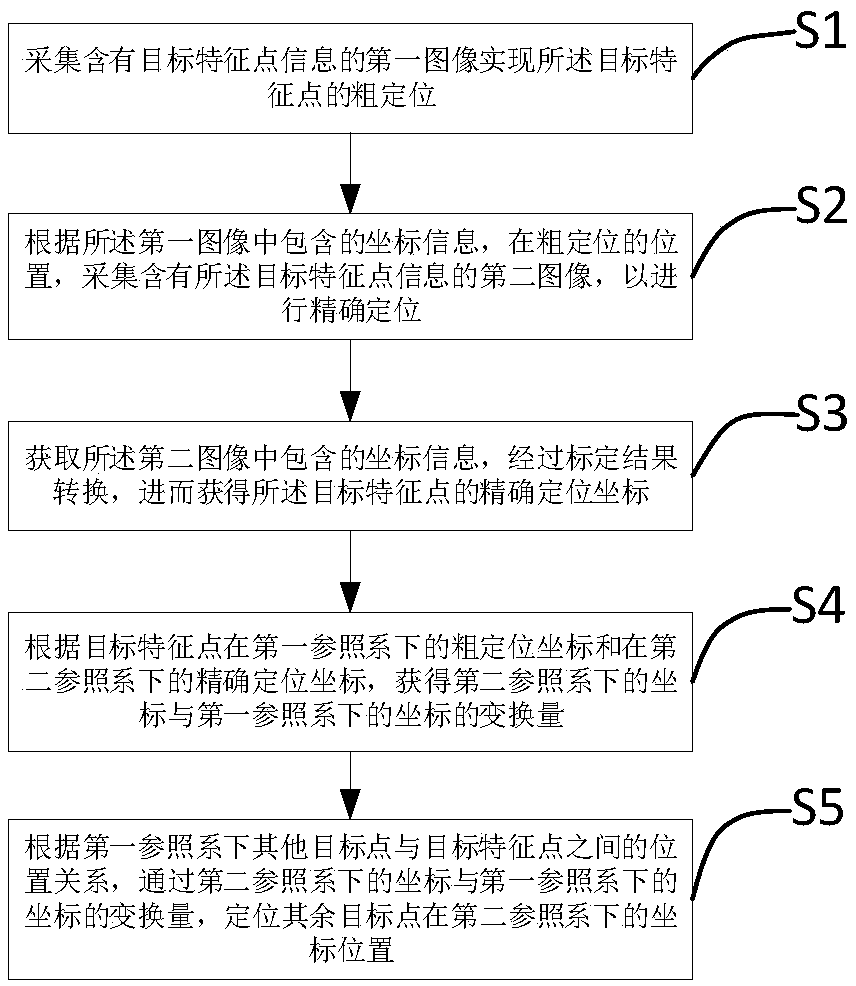
[0046] refer to figure 1 , is a flow chart of a step-by-step target positioning method based on vision fusion in Embodiment 1 of the present invention. The step-by-step positioning method of a target based on vision fusion in this embodiment includes the following steps:

[0047] S1. Acquiring a first image containing target feature point information to achieve rough positioning of the target feature point;

[0048] S2. According to the coordinate information contained in the first image, at the position of coarse positioning, collect the second image containing the target feature point information for fine positioning, specifically: acquire the first image containing the target feature point information After taking the image, by changing the range of the image acquisition field of view, the image acquisition of the target feature point is performed again, and the second image is obtained;

[0049] S3. Obtain the coordinate information included in the second image, and conv...

Embodiment 2

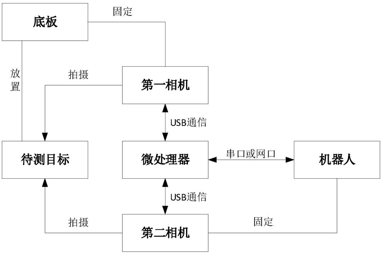
[0059] Figure 4 It is a schematic diagram of the robot coordinate system and the camera coordinate system in Embodiment 2 of the present invention. Wherein the SCARA manipulator includes a manipulator base 13 and a manipulator end 14, also includes a base plate 15, the origin 101 of the manipulator end coordinate system, the first camera 11 is a kind of Eye-to-hand camera, adopts a short focal length lens, and the second camera 12 is a An Eye-in-hand camera with a long focal length lens, the first camera 11 is responsible for the rough positioning of the large field of view, and the second camera 12 is responsible for the fine positioning of the small field of view, wherein the second camera 12 and the end 14 of the manipulator are connected by a rigid structure. As the tip 14 moves, the second camera 12 also moves.

[0060] Figure 5 It is a schematic diagram of a step-by-step target positioning method based on visual fusion in Embodiment 2 of the present invention. It tak...


PUM


Abstract

The invention discloses a method for positioning object step by step based on vision fusion, comprising collecting a first image containing target feature points to realize the coarse positioning of the target feature points, according to the coordinate information contained in the first image, collecting the second image containing the target feature point information, carrying out the precise positioning, obtaining the coordinate information contained in the second image, and obtaining the target feature point based on the coordinate transformation amount under the same coordinate system according to the conversion relationship between different coordinate systems, and locating the target feature point. At the same time, the invention also discloses an application, device and system forpositioning object step by step based on vision fusion. The scheme separates the positioning accuracy from the condition of large field of view, two different types of cameras are used to realize step-by-step positioning, which solves the problem that the positioning accuracy is insufficient when the workpiece moves in a large range; and when there are many screw holes, there is no need to take photographs repeatedly, which can reduce the number of photographs, improve the production efficiency, and has the advantages of high precision and high positioning efficiency.

Description

technical field [0001] The invention belongs to the technical field of visual positioning, and in particular relates to a step-by-step positioning method, application, device and system for a target based on visual fusion. Background technique [0002] The use of vision-guided robots for automatic screw locking is currently a popular solution for automated assembly production. Vision technology combined with industrial robots can improve the flexibility of robots. In the existing technical solutions, robots are equipped with a single vision system to achieve higher precision. The task of locking screws and allowing a certain movement of the workpiece to be assembled within the visual field of vision. [0003] For the existing screw machine positioning method, when the workpiece has a relatively large moving range, the positioning accuracy of the screw holes of this type of workpiece will decrease, and even the assembly task cannot be completed. If there are many screw holes ...

Claims


Application Information

Patent Timeline
Patent Type & Authority Applications(China)
IPC IPC(8): G06T7/73G06T1/00
CPCG06T1/0014G06T2207/10004G06T7/73
Inventor 田劲东胡荣镇李东田勇
Owner SHENZHEN UNIV
Why Eureka
Try Eureka