
High heat dissipation transformer

A high heat dissipation, transformer technology, applied in transformer/inductor casing, transformer/inductor cooling, transformer/inductor components, etc., can solve the problems of large amount of transformer heat, large vibration amplitude, transformer body pollution, etc., to achieve The structure is scientific and reasonable, the use is safe and convenient, and the effect of improving heat dissipation efficiency

Inactive Publication Date: 2019-03-08
江苏悦成变压器有限公司
View PDF0 Cites 0 Cited by
  • Summary
  • Abstract
  • Description
  • Claims
  • Application Information

AI Technical Summary

Problems solved by technology

[0003] The present invention provides a transformer with high heat dissipation, which can effectively solve the problem that the transformer in the above background technology generates a lot of heat during operation, which cannot be discharged in time, and cannot continue to dissipate heat. The transformer is not well sealed and dust and impurities enter its interior. Affect the normal operation of the transformer, and the staff forget to close the frame door, so that dust and water stains and other dirt from the outside will enter the inside of the transformer, polluting the inside of the transformer body, and vibration between the transformer body and the transformer shell due to large friction If the amplitude is too large, the transformer will not work properly and cause noise pollution problems

Method used


Image

  • High heat dissipation transformer
  • High heat dissipation transformer
  • High heat dissipation transformer

Examples


Embodiment Construction

[0023] The preferred embodiments of the present invention will be described below in conjunction with the accompanying drawings. It should be understood that the preferred embodiments described here are only used to illustrate and explain the present invention, and are not intended to limit the present invention.

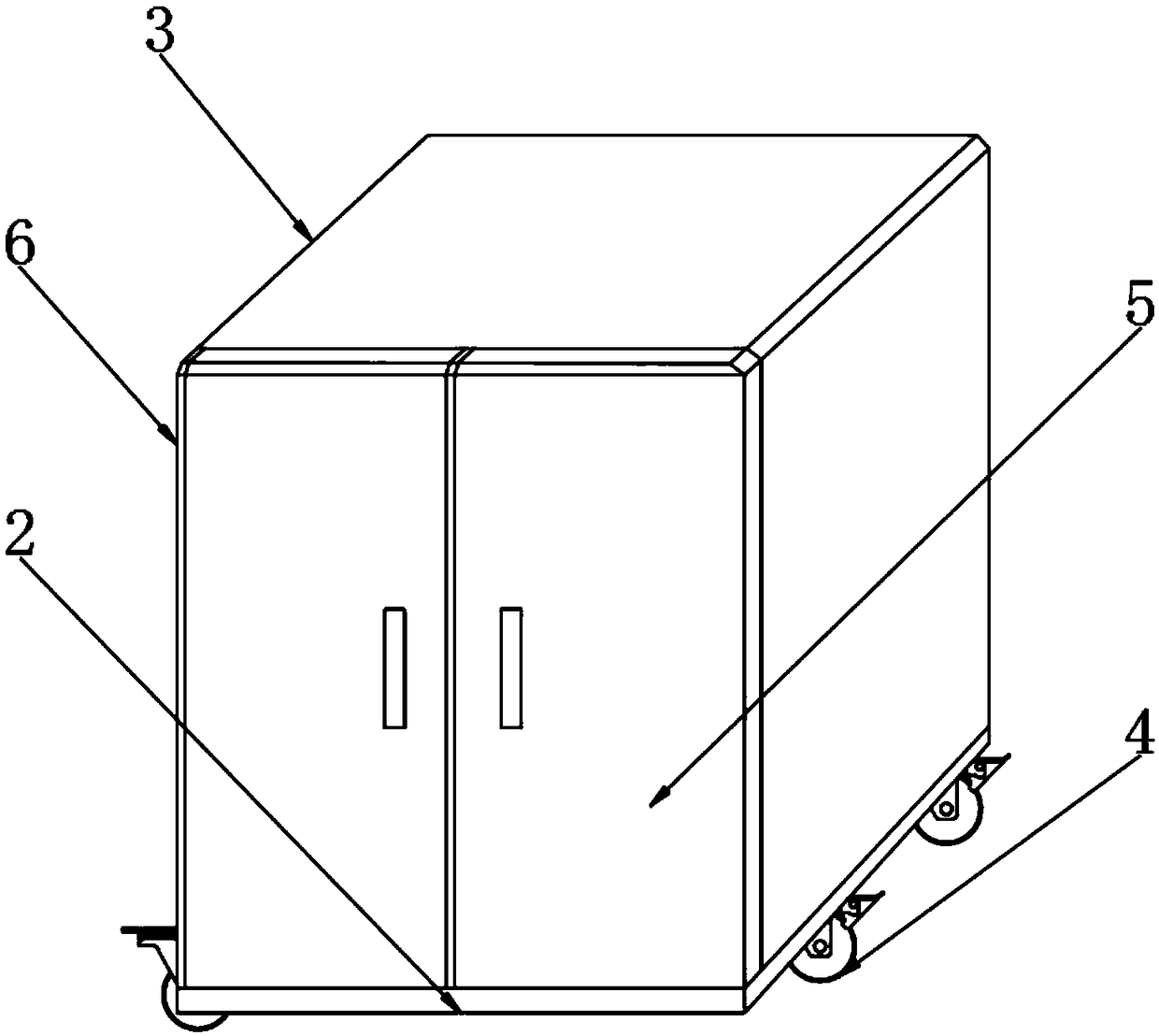
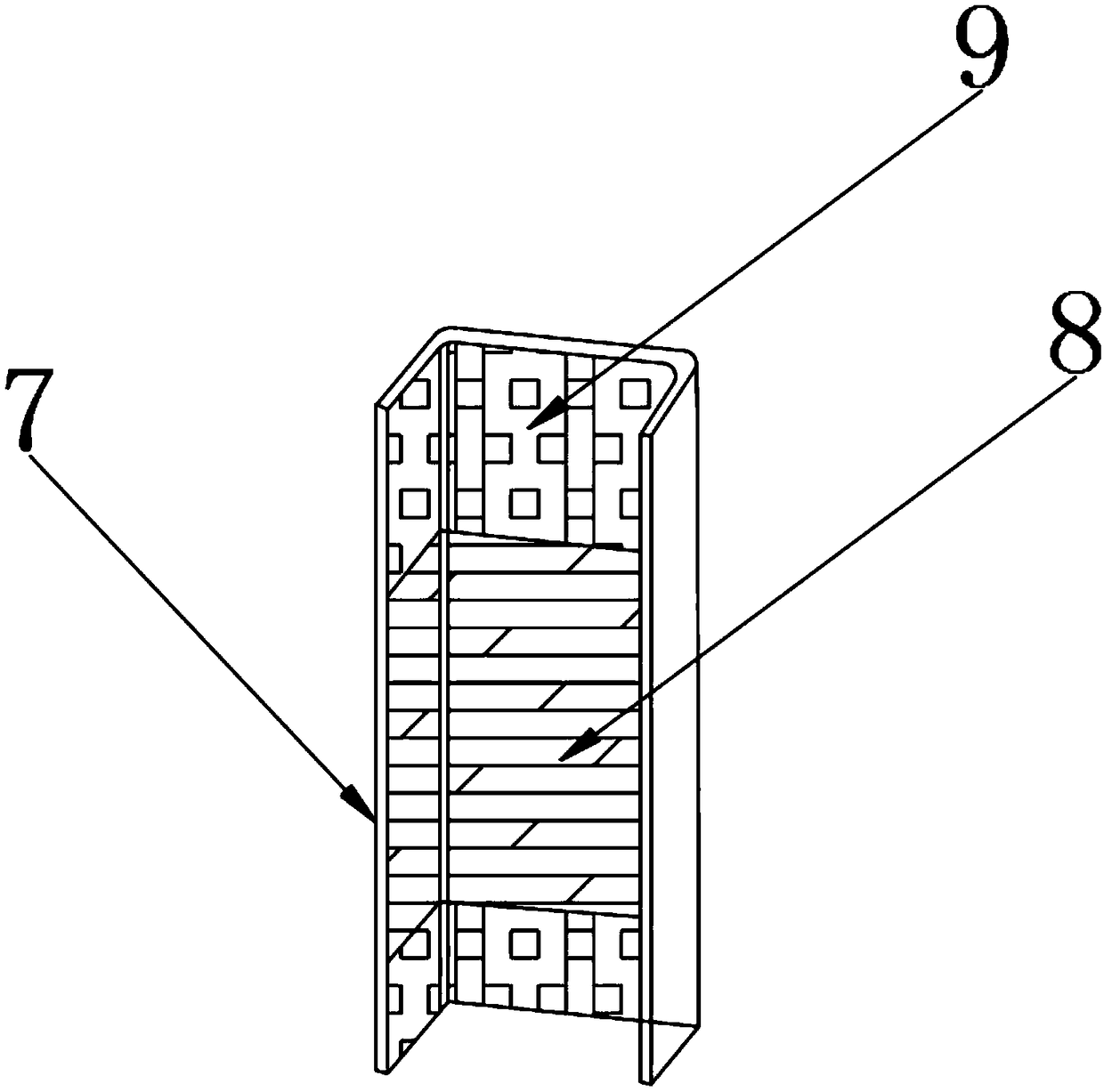
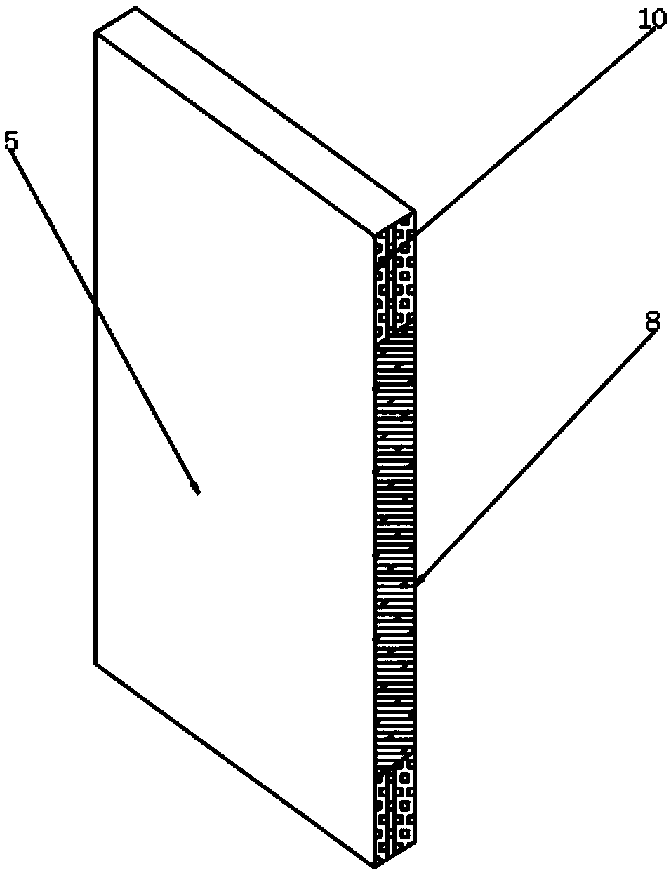
[0024] Example: such as Figure 1-4 As shown, the present invention provides a technical solution, a transformer with high heat dissipation, including a transformer body 1, a bottom plate 2, a transformer casing 3, a roller 4, a frame door 5, a frame 6, a fitting groove 7, a sealing strip 8, a positive Sexual magnet 9, negative magnet 10, heat dissipation fan chamber 11, heat dissipation fan 12, ventilation pipe 13, filter screen 14, baffle plate 15, condensation pipe 16, cooling hole 17, damping plate 18, damping spring 19, telescopic guide Column 20 and fixed end seat 21, bottom plate 2 is installed under the transformer body 1, transformer casing 3 is installed o...


PUM


Abstract

The invention discloses a high heat dissipation transformer. The transformer comprises a sealing strip, positive magnets, a frame door, a negative magnet, a transformer shell, a heat dissipating fan,a condensing tube, a vibration damper plate and a damping spring; both the upper end and the lower end of the sealing strip are equipped with the positive magnets; the negative magnet is installed inside the frame door; the heat dissipating fan is mounted above the transformer shell; the condensing tube is installed inside the transformer shell; and the damping spring is arranged inside the vibration damper plate. The high heat dissipation transformer is scientific and reasonable in structure, safe and convenient to use; the sealing strip, the positive magnet and the negative magnet are arranged so that the sealing performance of the transformer shell can be improved, and external dust and impurities are prevented from entering the inside of the transformer; the heat dissipating fan and the condensing tube are arranged so that the heat generated by the transformer body can be dissipated in time to prevent the phenomenon that the temperature is too high, causing short circuit and burning of the internal circuit of the transformer body; and the vibration damper plate and the damping spring are arranged so as to prevent the transformer body from affecting the stability thereof due toexcessive vibration amplitude.

Description

technical field [0001] The invention relates to the technical field of power equipment, in particular to a transformer with high heat dissipation. Background technique [0002] With the development of automation and intelligence in factories and family life, more and more electrical appliances have entered our lives, and the common work of these electrical appliances requires a stable voltage in order to make each electrical appliance work normally and provide our life. Bringing convenience, we often use transformers to stabilize voltage, and voltage regulators will generate a lot of heat when they are working. If the heat is not discharged and output in time, the transformer itself will affect its normal work due to excessive temperature. , the prior art transformer also has a heat dissipation function, but generally the heat dissipation performance is not good enough, so that the transformer can realize rapid heat dissipation, but it cannot make it continue to dissipate he...

Claims


Application Information

Patent Timeline
Patent Type & Authority Applications(China)
IPC IPC(8): H01F27/02H01F27/08F16F15/04
CPCH01F27/02F16F15/04H01F27/085
Inventor 董刚
Owner 江苏悦成变压器有限公司
Learn More