Stator core wire hanging framework, stator core and high-speed motor
A stator iron core and skeleton technology, applied in the field of stator iron core hanging wire skeleton and high-speed motor, can solve the problems of affecting the back EMF waveform, reducing motor efficiency, increasing harmonic components, etc., so as to improve motor efficiency, improve heat generation, and reduce iron consumption effect
- Summary
- Abstract
- Description
- Claims
- Application Information
AI Technical Summary
Problems solved by technology
Method used
Image

Examples
Embodiment 1
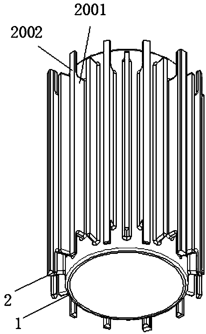
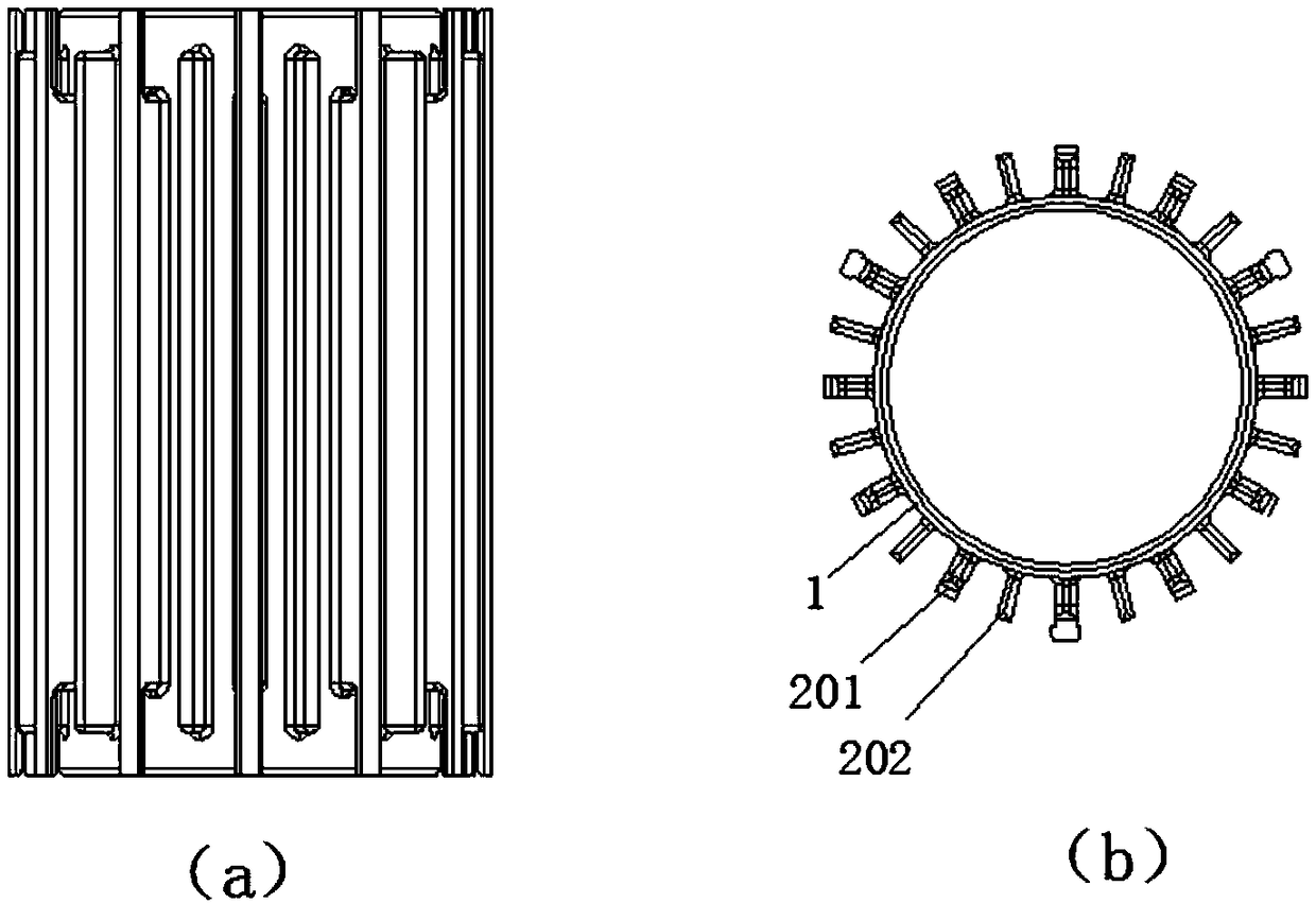
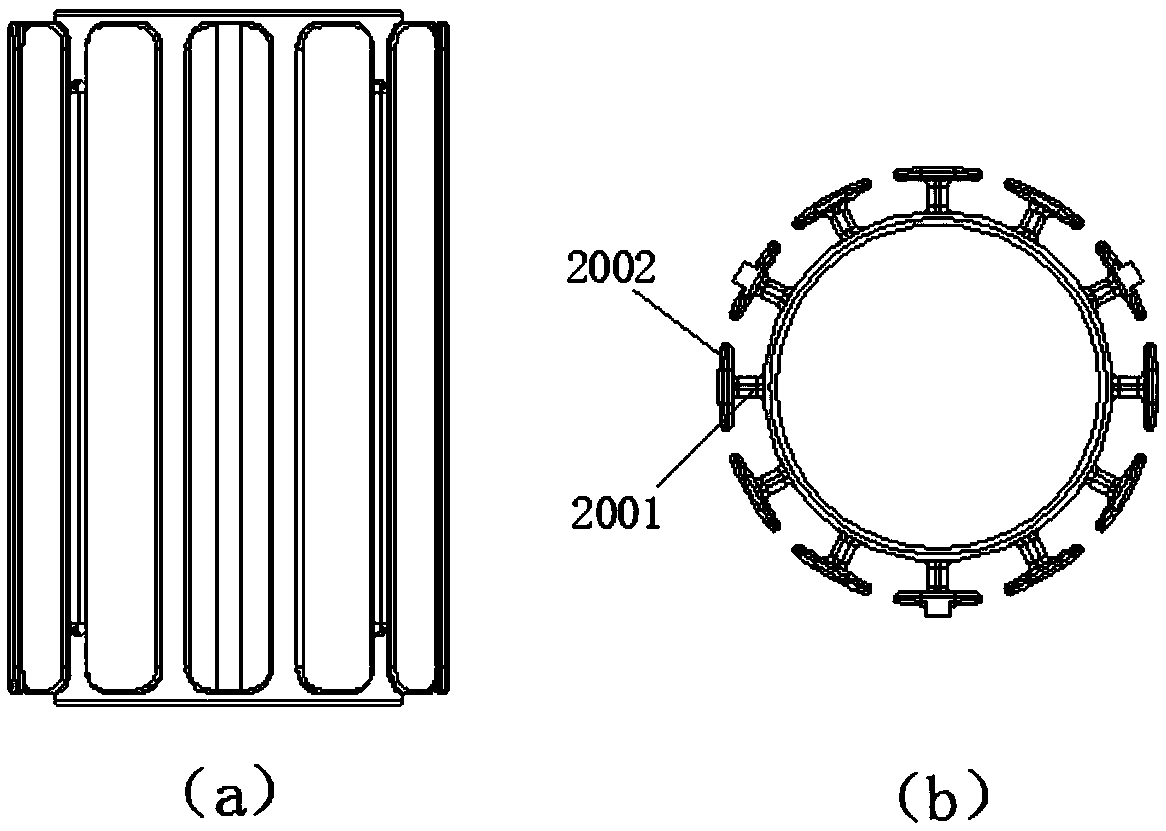
[0027] like figure 1 , figure 2 or image 3 As shown, the present embodiment provides a wire-hanging skeleton of a stator core, including a wire-hanging ring part 1, and a wire-hanging tooth part 2 is arranged on the outer peripheral surface of the wire-hanging ring part 1, and the wire-hanging tooth part 2 includes an even number Two hanging wire teeth 201 evenly distributed in the axial direction, and a wire hanging slot for placing the stator coil is formed between adjacent hanging wire teeth 201, wherein, the wire hanging ring part 1 and the wire hanging tooth part 2 are non-magnetic conduction Material.
[0028] It should be noted here that this embodiment is mainly used in high-speed motors or ultra-high-speed motors, specifically, it can be applied in high-speed brushless DC motors. Since high-speed motors or ultra-high-speed motors have very high current frequencies during operation, In order to reduce the iron loss, this embodiment provides a stator core hanging f...
Embodiment 2
[0036] like Figure 4 As shown, this embodiment provides a stator core, including a magnetically conductive ring part 3 and the stator core hanging frame provided in Embodiment 1, and the stator core hanging frame is installed on the inner peripheral surface of the magnetically conductive ring part 3 superior.
[0037] As an optimization, the inner peripheral surface of the magnetic conduction ring part 3 is provided with a positioning groove, and the wire hanging tooth part 2 of the stator core wire hanging frame is provided with a positioning convex edge, and the positioning convex edge is installed on the positioning in the slot.
[0038] As an optimization, one or more W-shaped grooves are arranged on the outer peripheral surface of the magnetic permeable ring part 3 in the axial direction.
[0039] What needs to be explained here is that the magnetically conductive ring part 3 in this embodiment can be laminated with silicon steel sheets, the positioning groove can be a...
Embodiment 3
[0041] like Figure 5 and Image 6 As shown, this embodiment provides a high-speed motor, including:
[0042] Stator, the stator includes the stator core provided in Embodiment 2; wherein, a stator coil is arranged in the wire hanging groove of the stator;
[0043] The rotor includes a rotor shaft 4 and a rotor core 5 sleeved on the rotor shaft 4, the rotor core 5 is located in the wire-hanging ring part 1 of the stator core, and the rotor shaft 4 is supported by at least one bearing 6 , the bearing is fixedly connected with the stator.
[0044] When specifically implementing this embodiment, the stator further includes a stator coil 7 , a housing 8 and a wiring device 9 connected to the stator coil 7 . The high-speed motor in this embodiment may be a high-speed brushless DC motor.
[0045]As an optimization, the rotor shaft 4 is provided with knurling at the junction with the rotor core 5 .
[0046] As an optimization, the bearing 6 is a gas bearing or an electromagnetic...
PUM
 Abstract
Description
Claims
Application Information
 - R&D
- Intellectual Property
- Life Sciences
- Materials
- Tech Scout
- Unparalleled Data Quality
- Higher Quality Content
- 60% Fewer Hallucinations
Browse by: Latest US Patents, China's latest patents, Technical Efficacy Thesaurus, Application Domain, Technology Topic, Popular Technical Reports.
© 2025 PatSnap. All rights reserved.Legal|Privacy policy|Modern Slavery Act Transparency Statement|Sitemap|About US| Contact US: help@patsnap.com