A Bootstrap Circuit for Precision Temperature Sensor

A technology of temperature sensor and bootstrap circuit, which is applied to parts of thermometers, thermometers, instruments, etc., can solve problems such as transient potential fluctuations, changes in input resistance of amplifying circuits, and influence on sensor detection accuracy, so as to improve input resistance, Reduce the amplitude and avoid the effect of mutual interference

Active Publication Date: 2020-08-14
瑞安市兆达机车部件有限公司
View PDF5 Cites 0 Cited by
  • Summary
  • Abstract
  • Description
  • Claims
  • Application Information

AI Technical Summary

Problems solved by technology

However, the traditional bootstrap circuit will have transient potential fluctuations in the process of input voltage changes, which will cause changes in the input resistance of the amplifier circuit and affect the detection accuracy of the sensor

Method used


Image

  • A Bootstrap Circuit for Precision Temperature Sensor
  • A Bootstrap Circuit for Precision Temperature Sensor

Examples


Embodiment 1

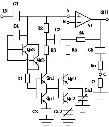
[0012] Reference figure 1 In a specific embodiment of the present invention, the input terminal IN is connected to the non-inverting input terminal of the first operational amplifier A1 through the first capacitor C1, and the non-inverting input terminal of the first operational amplifier A1 is respectively connected to the first NPN through the first resistor R1 The base of the transistor Qn1 and the first PNP transistor Qp1, the collector of the first NPN transistor Qn1 is connected to the positive phase input terminal of the first operational amplifier A1 through the second resistor R2 and the third resistor R3 connected in series, the first NPN transistor Qn1 The emitter of the first PNP transistor Qp1 is connected to the collector, the emitter of the first PNP transistor Qp1 is grounded through the third capacitor C3, and the second resistor R2 and the third resistor R3 are connected to the first device through the second capacitor C2. Put the inverting input terminal of A1...

Embodiment 2

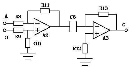
[0015] Reference Figure 1-2 , This embodiment is improved on the basis of embodiment 1. Since the filter capacitor in Embodiment 1 cannot adjust the filter state according to the change of the signal, further optimization is performed. A first sampling point A and a second sampling point B are respectively set at the non-inverting input terminal and the inverting input terminal of the first operational amplifier A1, and a sixth resistor R6 and a seventh resistor are set in series between the fifth capacitor C5 and the ground point R7, the first sampling point A is connected to the inverting input terminal of the second operational amplifier A2 through the eighth resistor R8, the second sampling point B is connected to the non-inverting input terminal of the second operational amplifier A2 through the ninth resistor R9, and the second The non-inverting input terminal of the operational amplifier A2 is grounded through the tenth resistor R10, the inverting input terminal of the...


PUM

PropertyMeasurementUnit
electrical resistanceaaaaaaaaaa

Abstract

The invention discloses a bootstrap circuit for a precise temperature sensor. An input end is connected to a non-inverting input end of a first operational amplifier through a first capacitor, the non-inverting input end of the first operational amplifier is connected to the bases of a first NPN audion and first PNP audion through first resistors separately, a collector of the first NPN audion isconnected to the non-inverting input end of the first operational amplifier through a second resistor and a third resistor which are in series connection, an emitter of the first NPN audion is connected to a collector of the first PNP audion, an emitter of the PNP audion is grounded through a third capacitor, the second resistor and the third resistor are connected to an inverting input end of thefirst operational amplifier through a second capacitor, the inverting input end of the first operational amplifier is connected to an output end of the first operational amplifier through a fourth resistor. The bootstrap circuit for the precise temperature sensor can overcome the deficiencies in the prior art, and reduces the amplitude of transient potential fluctuations occurring in the processof the input voltage change of the bootstrap circuit.

Description

Technical field [0001] The invention relates to a sensor drive circuit, in particular to a bootstrap circuit for precision temperature sensors. Background technique [0002] In the temperature sensor, the collected signal needs to be amplified and output to the subsequent circuit. In order to increase the input resistance of the amplifier circuit, a bootstrap circuit is usually required. However, the traditional bootstrap circuit will have transient potential fluctuations during the change of the input voltage, which will cause the input resistance of the amplifying circuit to change and affect the detection accuracy of the sensor. Summary of the invention [0003] The technical problem to be solved by the present invention is to provide a bootstrap circuit for a precision temperature sensor, which can solve the deficiencies of the prior art and reduce the amplitude of transient potential fluctuations in the bootstrap circuit during the input voltage change. [0004] To solve the ...

Claims


Application Information

Patent Timeline
Patent Type & Authority Patents(China)
IPC IPC(8): G01K1/00H03M1/12
CPCG01K1/00H03M1/12
Inventor 张超
Owner 瑞安市兆达机车部件有限公司
Why Eureka
Try Eureka