Bionic circuit and method for non-contact electrostatic potential distribution test

An electrostatic potential and non-contact technology, which is applied in the field of bionic circuits for non-contact electrostatic potential distribution testing, can solve the problems of improving the spatial resolution of the test method, not being able to improve the spatial resolution of the array density, and high input resistance. It is difficult to improve the test speed and spatial resolution at the same time, solve the effect of low spatial resolution and increase the array density

Active Publication Date: 2022-03-04
ARMY ENG UNIV OF PLA
View PDF18 Cites 0 Cited by
  • Summary
  • Abstract
  • Description
  • Claims
  • Application Information

AI Technical Summary

Problems solved by technology

[0003] The single-sensor scanning method improves the spatial resolution of the test results by reducing the scan step size, but with the increased test volume, the overall test speed is greatly reduced, and it is difficult to improve the test speed and spatial resolution at the same time
[0004] The sensor array is used in multi-sensor parallel mode, and the test speed is fast, but since the test electrode of each sensor has an independent ground shielding cylinder, the equivalent capacitance to the ground of the charged object under test will increase, resulting in electrostatic induction on the test electrode. Signal attenuation, when the attenuation is below the sensitivity of the conditioning amplifier circuit, the induction signal will be submerged by the background noise and cannot be picked up
[0005] In addition, in order to improve the spatial resolution of the measurement results of the non-contact electrostatic potential sensor, it is necessary to reduce the physical size of the sensing electrode, resulting in a decrease in the equivalent coupling capacitance between the sensing electrode and the charged object to be measured, reaching the level of picofarads or even femtofarads , which requires the signal amplifier circuit to have a very small input capacitance and a very high input resistance. The low input capacitance is used to match the equivalent coupling capacitance to improve the voltage division ratio and sensitivity. The time coefficient of the test result decay, which is the bottleneck problem that limits the improvement of the spatial resolution of the non-contact electrostatic potential test method
[0006] Therefore, the sensitivity of the amplification circuit limits the electrode size and array density of the sensor array, and the spatial resolution of parallel testing cannot be improved simply by reducing the electrode size and increasing the array density.

Method used


Image

  • Bionic circuit and method for non-contact electrostatic potential distribution test
  • Bionic circuit and method for non-contact electrostatic potential distribution test
  • Bionic circuit and method for non-contact electrostatic potential distribution test

Examples


Embodiment Construction

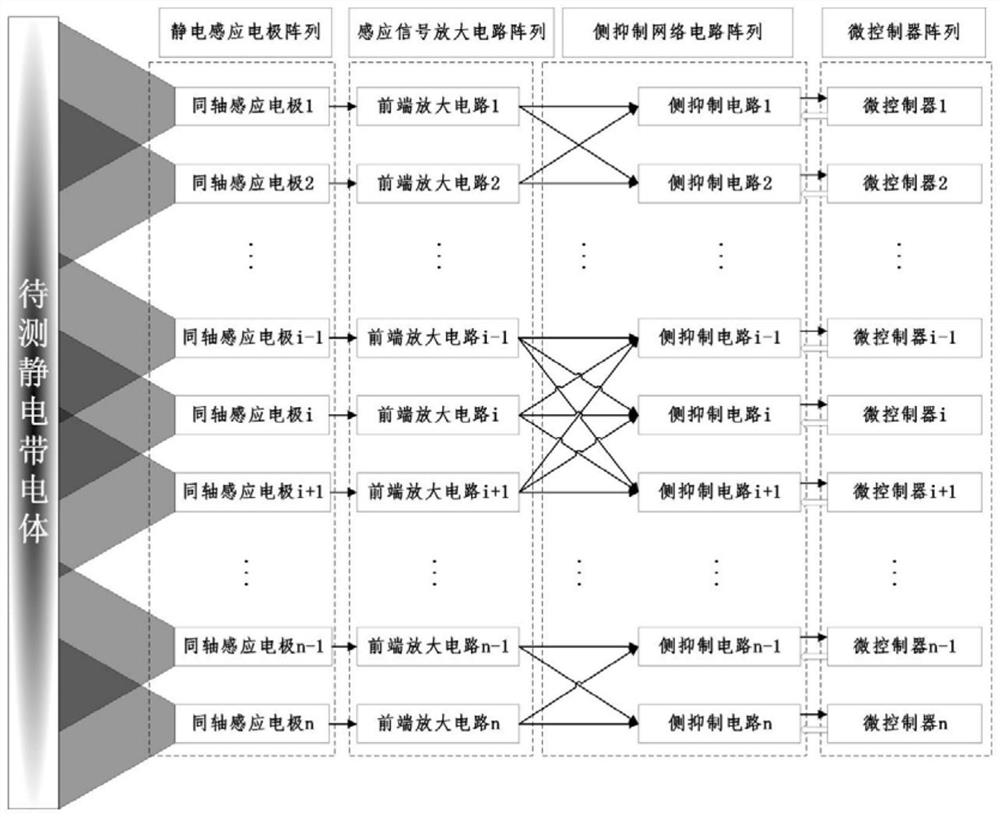
[0044] The present invention solves the test speed and spatial resolution of the non-contact electrostatic potential distribution test in combination with a multi-sensor parallel setting, solving the test speed and spatial resolution of the non-contact electrostatic potential distribution test.

[0045] The technical solutions of the present invention will be described below in conjunction with examples, as will be described herein, as described in the embodiments of the invention, not all embodiments. Based on the embodiments of the present invention, all other embodiments obtained by those of ordinary skill in the art are in the range of the present invention without making creative labor premise.

[0046]In the description of the present invention, it is necessary to understand that the term * # * center * # *, * # * portrait * # *, * # * horizontal * # *, * # * length * # *, * # * width * # *, * # * Thickness * # *, * # * on * # *, * # * *, * # * after * # *, * # * left * # * ...


PUM


Abstract

The invention discloses a bionic circuit and method for a non-contact electrostatic potential distribution test, and the circuit comprises an electrostatic induction electrode array which comprises N electrostatic induction electrodes; the induction signal amplification circuit array comprises N signal amplification circuits which are connected with the N electrostatic induction electrodes in a one-to-one manner; the side suppression network circuit array comprises N side suppression circuits, each side suppression circuit comprises two analog switch cross arrays with N input ends and N output ends, and each output end is connected with a side suppression weight sub-circuit; the output ends of the N signal amplification circuits are in many-to-many full connection with the analog switch cross array; the side suppression weight sub-circuits are respectively connected with a forward input end or a reverse input end of an amplifier, a resistor R-is connected between the reverse input end and an output end of the amplifier, and the forward input end is grounded through a resistor R +; the microcontroller array comprises N microcontrollers which are connected with the N side suppression network circuits in a one-to-one manner; and the side suppression weight sub-circuit is connected with the analog switch cross array and the side suppression weight sub-circuit.

Description

Technical field [0001] The present invention relates to an electrostatic potential distribution test technology, and more particularly to a bionic circuit and method for non-contact electrostatic potential distribution test. Background technique [0002] The non-contact electrostatic potential test is based on the electrostatic induction principle, by measuring the distortion of the tapered body and the induction electrode, indirectly obtains an electrostatic potential of the charged body, and is existing with a non-contact electrostatic potential sensor to achieve high electrostatic potential space distribution. The resolution test method mainly has a single sensor scan and a multi-sensor parallel, of which [0003] Single-sensor scanning mode By reducing the spatial resolution of the test results, accompanied by increased test volume reduces the overall test speed, it is difficult to improve test speed and spatial resolution. [0004] Multi-sensor parallelism uses sensor arrays...

Claims


Application Information

Patent Timeline
Patent Type & Authority Applications(China)
IPC IPC(8): G01R29/14G01R29/24
CPCG01R29/14G01R29/24
Inventor 满梦华魏明冯亚辉
Owner ARMY ENG UNIV OF PLA
Why Eureka
Try Eureka