
Automotive fuel system for substantially reducing hydrocarbon emissions into the atmosphere, and method

a fuel system and hydrocarbon emission technology, applied in the direction of condensed fuel collection/return, charge feed system, non-fuel substance addition to fuel, etc., can solve the problem that the adsorbent bed capacity of the prior device cannot be effectively utilized, and achieve the effect of reducing the required size of the emissions canister, reducing the emission of fuel vapor, and increasing the efficiency of the adsorbent material

Inactive Publication Date: 2008-12-18
FLUID ROUTING SOLUTIONS
View PDF54 Cites 22 Cited by
  • Summary
  • Abstract
  • Description
  • Claims
  • Application Information

AI Technical Summary

Benefits of technology

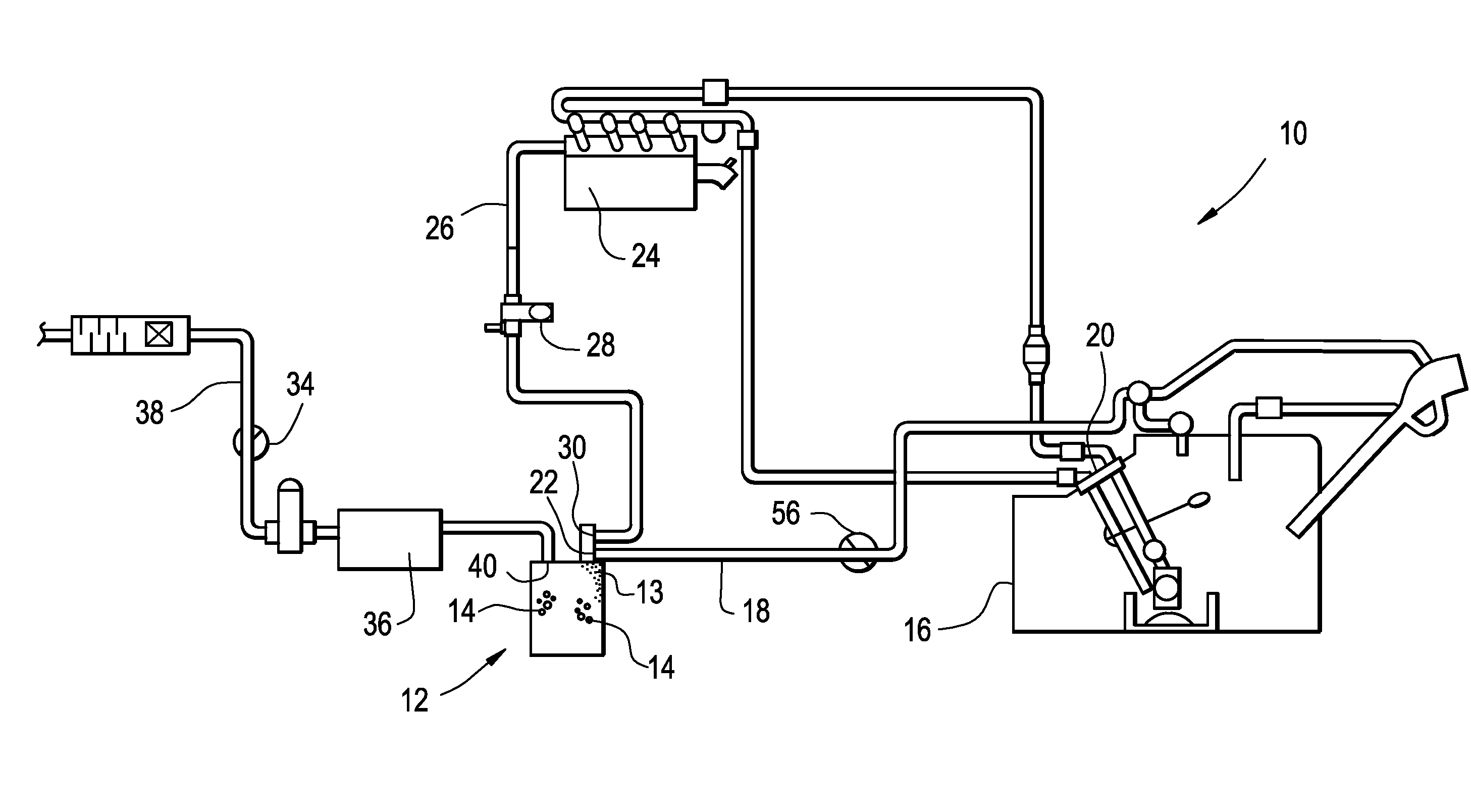
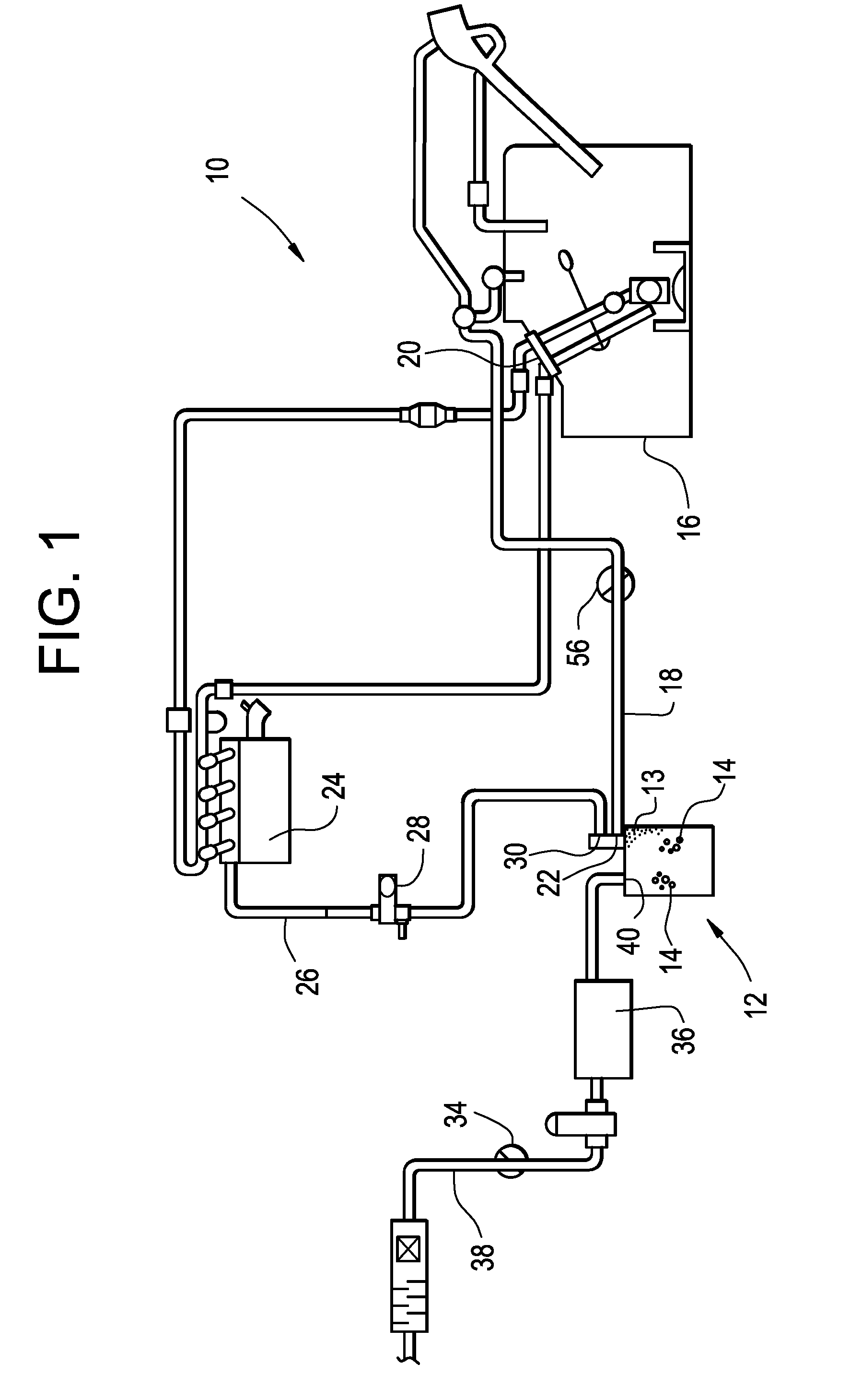
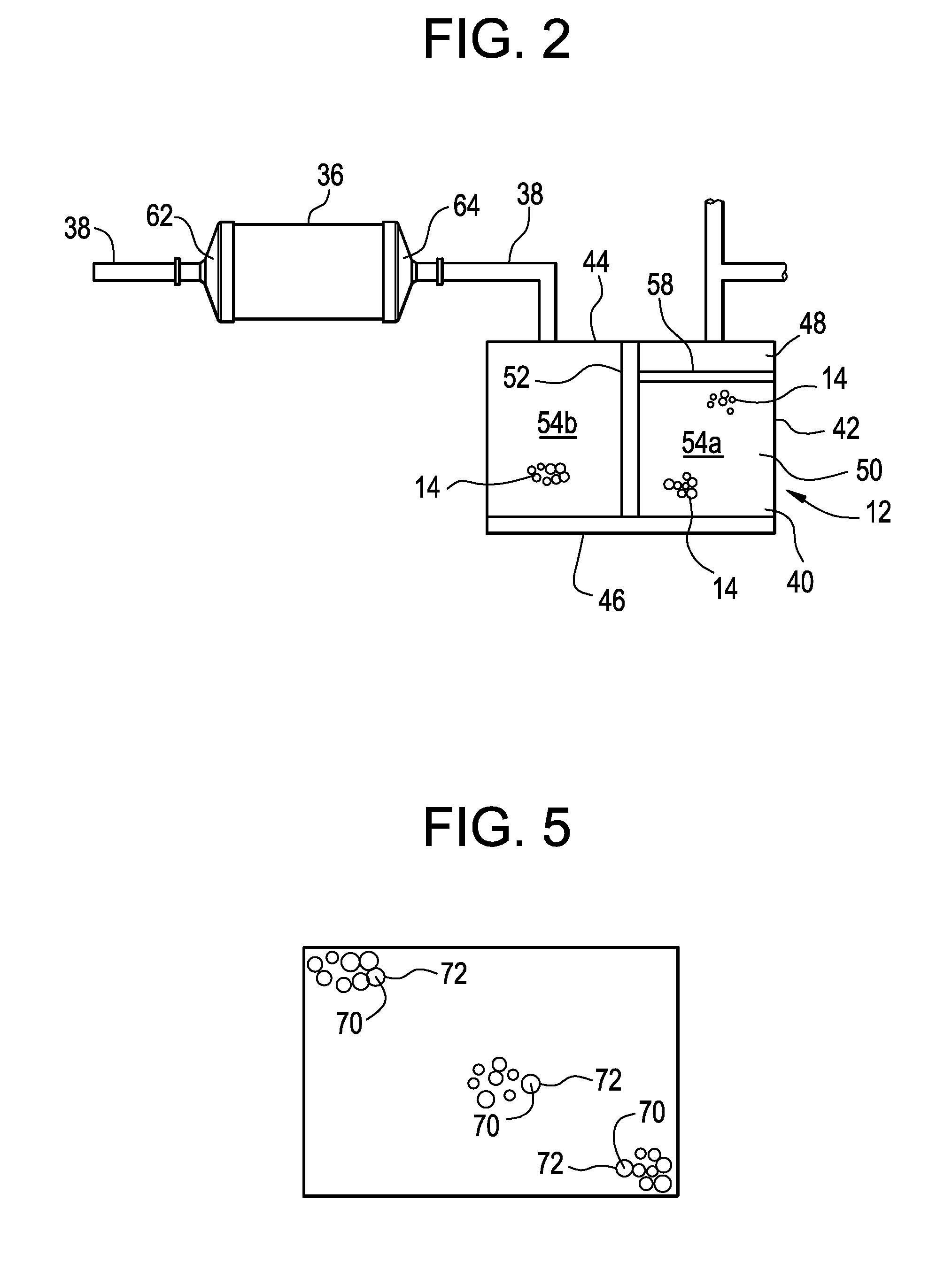
[0006]It has been found that a carbon-coated reticulated foam material disposed in a housing module and employed externally in the fresh air line of an emissions canister effectively prevents the emission of any fuel vapor molecules through the carbon-coated reticulated foam material while allowing air molecules to pass freely therethrough. Furthermore, it has been found that the use of an external module containing the carbon-coated, reticulated foam material in conjunction with a separate emissions canister not only substantially reduces the emission of fuel vapors to the atmosphere, but the use of the external auxiliary module also increases the efficiency of the adsorbent material in the emissions canister allowing a substantial reduction in the required size of the emissions canister. More specifically, the evaporative emissions canister of the present invention incorporates the carbon-coated reticulated material on the vent or fresh air side of the evaporative emissions canister in the vent or fresh air inlet / outlet port. By installing the carbon-coated reticulated material at the vent or fresh air inlet / outlet port, the external housing containing the carbon-coated reticulated material allows the entire adsorbent bed to be utilized for adsorbing fuel vapor as opposed to prior canisters which effectively utilize only a portion of the adsorbent material contained in the canister for the purpose of adsorbing the fuel vapor. In conventional canisters, a portion of the adsorbent material is used as a buffer on the vent side of the canister. Accordingly, prior devices do not effectively utilize the entire capacity of the adsorbent bed.
[0007]In accordance with the present invention, the use of an external auxiliary housing prevents all or substantially all of the fuel vapor molecules from escaping into the atmosphere while improving the efficiency of the adsorbent material in the emissions canister, thereby reducing the size requirements for the emissions canister and providing increased flexibility in the overall configuration of the emissions system due to the use of separate and smaller components.
[0008]Accordingly, it is a primary object of this invention to provide an improved evaporative emissions system, which incorporates a carbon-coated foam material in a housing external with respect to the evaporative emissions canister wherein the full capacity of the adsorbent material can be effectively utilized.
[0009]It is another object of the invention to provide an evaporative emissions canister that provides reduced fuel emissions to the atmosphere.
[0010]It is still another object of the invention to optimize the overall packaging of the evaporative emissions system by allowing the external housing to be more efficiently configured and located in the emissions system.
[0012]It is another object of the invention to provide all of the above objects of the invention without severe complexity and economic strain.

Problems solved by technology

Accordingly, prior devices do not effectively utilize the entire capacity of the adsorbent bed.

Method used


Image

  • Automotive fuel system for substantially reducing hydrocarbon emissions into the atmosphere, and method
  • Automotive fuel system for substantially reducing hydrocarbon emissions into the atmosphere, and method
  • Automotive fuel system for substantially reducing hydrocarbon emissions into the atmosphere, and method

Examples


Embodiment Construction

[0019]The carbon-coated reticulated adsorbent material employed in the present invention exhibits appropriate physical characteristics which enables the carbon-coated, reticulated foam material to effectively prevent all or substantially all of the fuel vapors from being emitted to the atmosphere. The carbon-coated, reticulated foam material effectively prevents about 95% or more of the residual fuel vapor molecules in the air flow from being emitted to the atmosphere while allowing greater than about 99% of the air molecules to be emitted to the atmosphere. Typically, the carbon-coated, reticulated foam material of the present invention has an effective pore count of about 45 to 300 pores per inch, and preferably, about 50 to 100 pores per inch. Carbon-coated, reticulated foams are disclosed in U.S. pat. appln. No. US 2006 / 0205830, filed Sep. 14, 2006, the contents of which is incorporated herein by reference thereto. Accordingly, the carbon-coated reticulated material effectively ...


PUM


Abstract

An evaporative emissions system is used in an automotive evaporative emission system including a fuel tank coupled to an automotive engine to control emission of fuel vapors to the atmosphere. The system includes an evaporative emissions canister comprising a first molded housing having a circumferential side member, a top member and a bottom member; a hydrocarbon-adsorbing material disposed therein so as to provide a vapor adsorbent chamber for adsorbing hydrocarbon fuel vapor flowing therethrough; and an auxiliary housing containing a carbon-coated reticulated material, the reticulated housing located in the fresh air line of the evaporative emissions canister for preventing fuel vapor molecules from passing through the carbon-coated reticulated material while allowing the air molecules to pass therethrough. A method is provided for preventing or reducing hydrocarbon emissions to the atmosphere.

Description

BACKGROUND OF THE INVENTION[0001]The present invention relates to a fuel system for an internal combustion engine; particularly, to an evaporation emissions system and for preventing or substantially reducing the emission of hydrocarbon pollutants into the atmosphere; and most particularly, to an improved evaporative emissions system having an external module containing a carbon-coated foam material which acts as a filter media to prevent or substantially reduce the emission of hydrocarbon fuel pollutants to the atmosphere. The module containing the carbon-coated foam material is external with respect to the evaporative emissions canister and, more particularly, in the path of fresh air entering or exiting the emissions canister.[0002]Evaporative emissions result from any one of several events which includes venting of fuel vapors from the fuel tank due to diurnal changes in ambient pressure and / or temperatures (known in the art as “diurnal” emissions), by refueling of the vehicle (...

Claims


Application Information

Patent Timeline
IPC IPC(8): F02M33/08
CPCF02M25/0854F02M25/089
Inventor ALLEN, CHRISTOPHER D.DUMAS, JAMES T.GEPPER, DONALD L.
Owner FLUID ROUTING SOLUTIONS
Learn More