Defect detection device and defect detection method

A defect detection and equipment technology, applied in the field of optical detection, can solve the problems of destructiveness and low efficiency

Active Publication Date: 2019-03-12
LASER FUSION RES CENT CHINA ACAD OF ENG PHYSICS
View PDF11 Cites 16 Cited by
  • Summary
  • Abstract
  • Description
  • Claims
  • Application Information

AI Technical Summary

Problems solved by technology

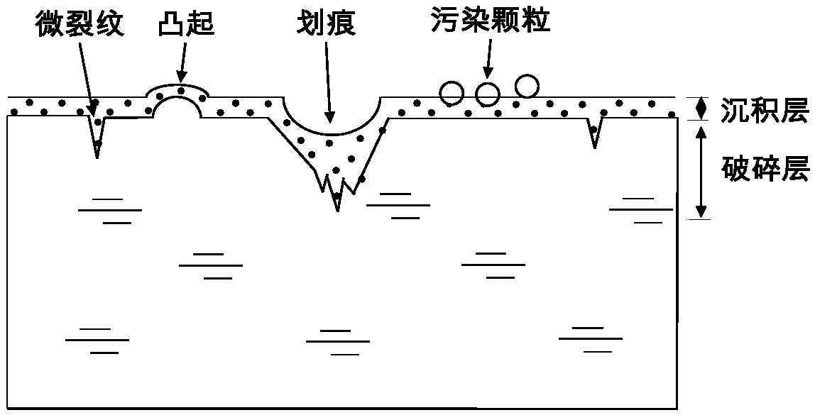
[0003] However, the existing subsurface defect detection methods are to expose defects of different depths through physical or chemical methods, and combine optical microscopy, scanning electron microscopy, atomic force microscopy and other technologies to obtain defect information. These methods test subsurface defects with high precision , not affected by surface defects, widely used in the processing industry, but there are problems such as low efficiency and destructiveness

Method used


Image

  • Defect detection device and defect detection method
  • Defect detection device and defect detection method
  • Defect detection device and defect detection method

Examples


Embodiment Construction

[0025] In order to make the purpose, technical solutions and advantages of the embodiments of the present invention clearer, the technical solutions in the embodiments of the present invention will be clearly and completely described below in conjunction with the drawings in the embodiments of the present invention. Obviously, the described embodiments It is a part of embodiments of the present invention, but not all embodiments. The components of the embodiments of the invention generally described and illustrated in the figures herein may be arranged and designed in a variety of different configurations.

[0026] Accordingly, the following detailed description of the embodiments of the invention provided in the accompanying drawings is not intended to limit the scope of the claimed invention, but merely represents selected embodiments of the invention. Based on the embodiments of the present invention, all other embodiments obtained by persons of ordinary skill in the art wi...


PUM


Abstract

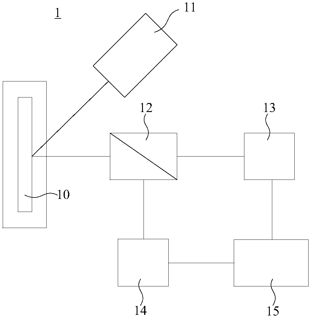
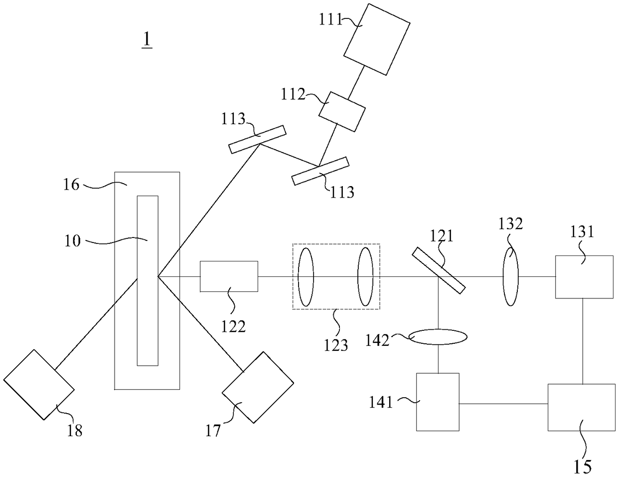
The invention provides a defect detection device and a defect detection method. Probe light is emitted by a laser emitting device, and is enabled to be irradiated onto a sample to be tested, so that signal light is formed; then, the scattered light and fluorescent light, which are contained in the signal light, are separated by means of a spectroscopic device, so that the fluorescent light is incident on a first detecting device for imaging, the scattered light is incident on a second detecting device for imaging, and fluorescent image information acquired by the first detecting device and scattered light image information acquired by the second detecting device are further processed by means of a control device; therefore, the surface defect information and subsurface defect information of the sample to be tested are obtained. After the technical scheme is adopted, the non-destructive detection of the subsurface defects of the sample to be tested can be realized, and the non-destructive detection of the surface defects of the sample to be tested can be simultaneously realized, so that the reduction of the test time of the defect detection is facilitated, and the test efficiency isincreased.

Description

technical field [0001] The invention relates to the technical field of optical detection, in particular to a defect detection device and method. Background technique [0002] In order to obtain maximum output, large-scale high-power / high-energy laser devices operate at a flux close to the damage threshold of optical components, so the damage performance of optical components is particularly important, which is the key to determining the output capability of such laser devices. At present, most of the damage problems of optical components under high-throughput can be attributed to various defects on the subsurface of optical components. These defects have a depth of several microns to hundreds of microns. damage. Therefore, detection techniques and methods for subsurface defects of optical components are very critical. [0003] However, the existing subsurface defect detection methods are to expose defects of different depths through physical or chemical methods, and combin...

Claims


Application Information

Patent Timeline
Patent Type & Authority Applications(China)
IPC IPC(8): G01N21/88G01N21/64G01N21/47G01N21/01
CPCG01N21/01G01N21/47G01N21/6428G01N21/643G01N21/88G01N21/8806G01N21/8851G01N2021/0112
Inventor 刘红婕王凤蕊黄进周晓燕叶鑫黎维华孙来喜石兆华夏汉定邓清华邵婷
Owner LASER FUSION RES CENT CHINA ACAD OF ENG PHYSICS
Why Eureka
Try Eureka