A method for predict a path and distance traveling along a plane base on a plurality of camera lenses

A travel path, camera technology, applied in the field of pattern recognition to compensate for jitter and instability

Pending Publication Date: 2019-03-12
依睿迪亚(南京)智能科技有限公司
View PDF4 Cites 0 Cited by
  • Summary
  • Abstract
  • Description
  • Claims
  • Application Information

AI Technical Summary

Problems solved by technology

[0004] The technical problem to be solved by the present invention is to provide a method for estimating the travel path and distance along the plane based on multiple camera lenses, multi-directional positioning of th

Method used


Image

  • A method for predict a path and distance traveling along a plane base on a plurality of camera lenses
  • A method for predict a path and distance traveling along a plane base on a plurality of camera lenses
  • A method for predict a path and distance traveling along a plane base on a plurality of camera lenses

Examples


Example Embodiment

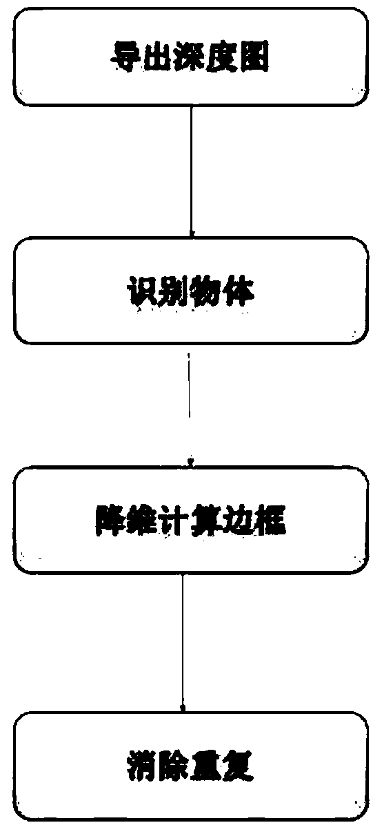
[0021] Such as figure 1 As shown, a method for estimating the path and distance along a plane based on multiple camera lenses includes the following steps:

[0022] (1) Export the depth map of each camera's 3D coordinate mapping;

[0023] (2) Find out the target object to be observed in each camera;

[0024] (3) For each target problem found, calculate the bounding box and use the depth map to map the point at the bottom edge center to the bottom 2-D plane;

[0025] (4) Eliminate duplicate target objects to obtain a complete location list.

[0026] In step (1), deriving the depth map of each camera's 3D coordinate mapping specifically includes the following steps:

[0027] (11) A known object moves continuously in the camera view, and calculates its distance according to its size, until all parts of the viewport have been mapped;

[0028] (12) When the camera is pointed at a flat field or pitch at a specific angle, the depth map is simply pre-programmed when it is known;

[0029] (13) The ...


PUM


Abstract

The invention discloses a method for estimating a path and a distance traveling along a plane based on a plurality of camera lenses, which comprises the following steps: (1) deriving a depth map of three-dimensional coordinate mapping of each camera; (2) finding out the object to be observed in each camera; (3) For each found target problem, the bounding box is computed and the point in the centerof its lower edge is mapped to the bottom 2-D plane; (4) Eliminating duplicates of the target object to obtain a complete list of positions. The invention discloses a novel visualization method, which distinguishes the same object photographed by different cameras through a mapping dimension reduction method, and directly reproduces the moving track of the object in a certain large area. Multiplepositioning cameras not only make up for the outdoor space can not be installed high position camera alone, but also make up for the shake and instability of the unmanned aerial vehicle cameras.

Description

technical field [0001] The invention relates to the technical field of pattern recognition, in particular to a method for estimating a traveling path and distance along a plane based on multiple camera lenses. Background technique [0002] The most convenient way to visualize a space is usually a top-down view, whether in the form of a map, a blueprint, or a bird's-eye view. This is typically used in a variety of applications, such as studying the direction of foot traffic in a shopping mall, the changing position of a soccer player on a pitch, or the attack paths of opposing armies in historical battle scenarios. However, creating such a display is often a complex task, and the unsteady-flying drone camera is too low to be suitable for indoor spaces; the camera is installed in a high position and cannot be extended outdoors. Therefore, one often needs indirect methods for such mappings. [0003] Now imagine an area scene, such as a football field, with multiple camera per...

Claims


Application Information

Patent Timeline
IPC IPC(8): G06T7/292G06T7/50G06T7/70
CPCG06T7/292G06T7/50G06T7/70G06T2207/10021
Inventor 拉里
Owner 依睿迪亚(南京)智能科技有限公司
Why Eureka
Try Eureka