A frequency offset compensation method and device

A technology of frequency offset compensation and frequency offset, which is applied in the field of frequency offset compensation methods and devices, can solve problems such as unavailability of high-speed mobile communication links, failure of terminal solutions, and difficulties in implementing solutions, so as to compensate for instability and reduce performance requirements , easy-to-achieve effects

Active Publication Date: 2022-07-12
CHENGDU TD TECH LTD
View PDF4 Cites 0 Cited by
  • Summary
  • Abstract
  • Description
  • Claims
  • Application Information

AI Technical Summary

Problems solved by technology

Usually, the clock of the terminal is locked on the downlink pilot of the base station. For high-speed scenarios, the uplink signal will reach the base station with twice the Doppler frequency deviation (such as figure 1 shown), resulting in link unavailability during high-speed mobile communication
[0003] The supported movement speed of 5G planning is 500km / h. For higher-speed communication (such as aircraft and ground communication), the speed can reach up to 1200km / h. The current 4G / 5G air interface standards cannot support it.
If the GPSDO solution is adopted, the terminal needs to install a GPS antenna or obtain a GPS reference clock source, which will lead to complex terminal design and increased cost
[0008] The above-mentioned second solution needs to obtain the terminal’s position, speed and base station’s position. On the one hand, the design of the terminal will be complicated; on the other hand, when the system adds a new base station, if the corresponding system data is not updated in time, it will Cause the original solution of the terminal to fail, therefore, it will also cause difficulties in the implementation of the solution

Method used


Image

  • A frequency offset compensation method and device
  • A frequency offset compensation method and device
  • A frequency offset compensation method and device

Examples


Embodiment Construction

[0053] In order to make the objectives, technical solutions and advantages of the present invention clearer, the present invention will be further described in detail below with reference to the accompanying drawings and specific embodiments.

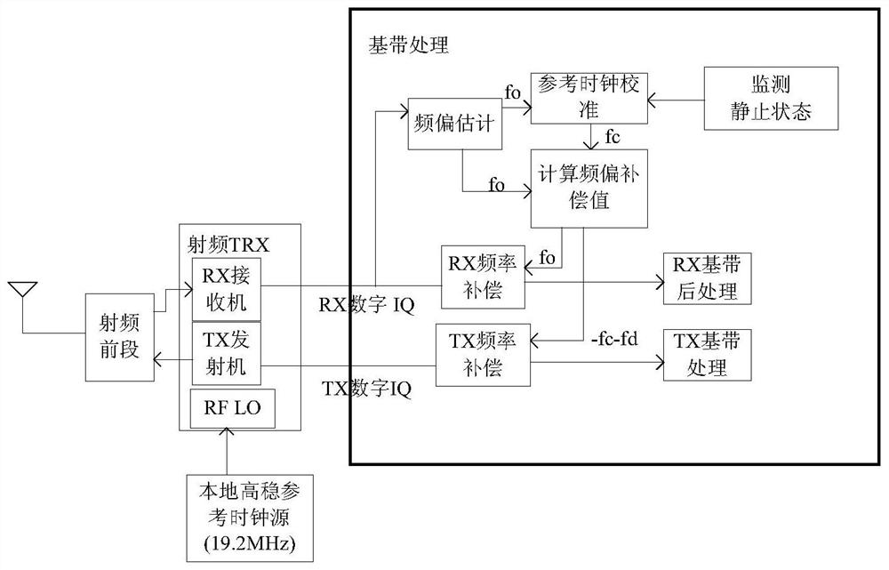
[0054] figure 2 A schematic diagram of the principle of the present invention is given, such as figure 2As shown, the present invention will introduce a reference clock into the terminal, which can maintain frequency stability for a period of time (for example, 24-hour frequency accuracy can be maintained at 0.005ppm). When the terminal is stationary, the downlink pilot frequency of the base station can be used to reference the reference The clock performs frequency calibration, thereby reducing the cost of the reference clock source and reducing the dependence on external reference sources such as GPS, which can effectively reduce the implementation cost of frequency compensation.

[0055] image 3 It is a schematic flowchart of a ...


PUM


Abstract

The present application discloses a frequency offset compensation method and device, wherein the method includes: when the terminal equipment monitors that the terminal is in a static state, triggering frequency calibration of the reference clock of the equipment according to the current frequency offset fo of the receiving link, to obtain the current The reference clock frequency offset value fc; when the terminal equipment receives data, it estimates the received frequency offset according to the received pilot frequency or demodulation reference signal, and obtains the current receiving link frequency offset fo; The reference clock frequency offset value fc and the receiving link frequency offset fo are used to calculate the current receiving frequency offset compensation value and the sending frequency offset compensation value; the terminal device uses the current receiving frequency offset compensation value and the sending frequency offset compensation value. Frequency offset compensation value, respectively perform frequency offset compensation on the data on the corresponding link. The present invention can effectively solve the problem of Doppler frequency shift in high-speed environment, and is low in cost and easy to implement.

Description

technical field [0001] The present invention relates to mobile communication technology, in particular to a frequency offset compensation method and device. Background technique [0002] With the development of society and mobile communications, requirements for communications in high-speed environments are also raised. Usually, the clock of the terminal is locked on the downlink pilot frequency of the base station. For high-speed scenarios, the Doppler frequency offset of 2 times when the uplink signal arrives at the base station (such as figure 1 shown), resulting in link unavailability during high-speed mobile communication. [0003] The 5G plan supports a movement speed of 500km / h. For higher-speed communication (such as aircraft and ground communication), the maximum speed can reach 1200km / h, which cannot be supported by the current 4G / 5G air interface standards. In response to this problem, the following solutions have been proposed. [0004] One is to introduce a h...

Claims


Application Information

Patent Timeline
Patent Type & Authority Patents(China)
IPC IPC(8): H04L27/00H04L25/02H04J3/06H04L7/00
CPCH04L27/0014H04L25/0224H04J3/0638H04L7/0079H04L2027/0026Y02D30/70
Inventor 熊兵佟学俭徐绍君
Owner CHENGDU TD TECH LTD
Why Eureka
Try Eureka