
Baud rate calibration method and calibration circuit of CAN controller

A technology of CAN controller and calibration method, which is applied in the field of intelligent robots, can solve the problems of CAN nodes not working normally, communication cannot be guaranteed, and flexibility is not high, so as to make up for unstable factors, improve flexibility, and improve adjustment accuracy.

Pending Publication Date: 2022-04-12
AMICRO SEMICON CORP
View PDF7 Cites 1 Cited by
  • Summary
  • Abstract
  • Description
  • Claims
  • Application Information

AI Technical Summary

Problems solved by technology

However, when the on-chip RC oscillator is selected, the frequency will cause an error of about ±3% due to external factors such as temperature, and the stability of the frequency is also worse than that of the external crystal oscillator. Setting the baud rate parameters according to the theoretical calculation value cannot guarantee CAN reliability. Communication
The simple way for the CAN controller is to set the CAN nodes to the same baud rate, but this is not very flexible. If the RC error is too large, the CAN nodes may not work properly.

Method used


Image

  • Baud rate calibration method and calibration circuit of CAN controller
  • Baud rate calibration method and calibration circuit of CAN controller

Examples


Embodiment Construction

[0019] The technical solutions in the embodiments of the present invention will be described in detail below with reference to the drawings in the embodiments of the present invention. It should be understood that the specific embodiments described below are only used to explain the present invention, not to limit the present invention. It should be understood that the specific embodiments described here are only used to explain the present invention, and are not intended to limit the present application. Based on the embodiments provided in this application, all other embodiments obtained by persons of ordinary skill in the art without creative efforts fall within the protection scope of this application.

[0020] The terminology used herein is for the purpose of describing particular embodiments only, and is not intended to be limiting of the present disclosure. The terms "comprising", "comprising" and the like used herein indicate the presence of stated features, operation...


PUM


Abstract

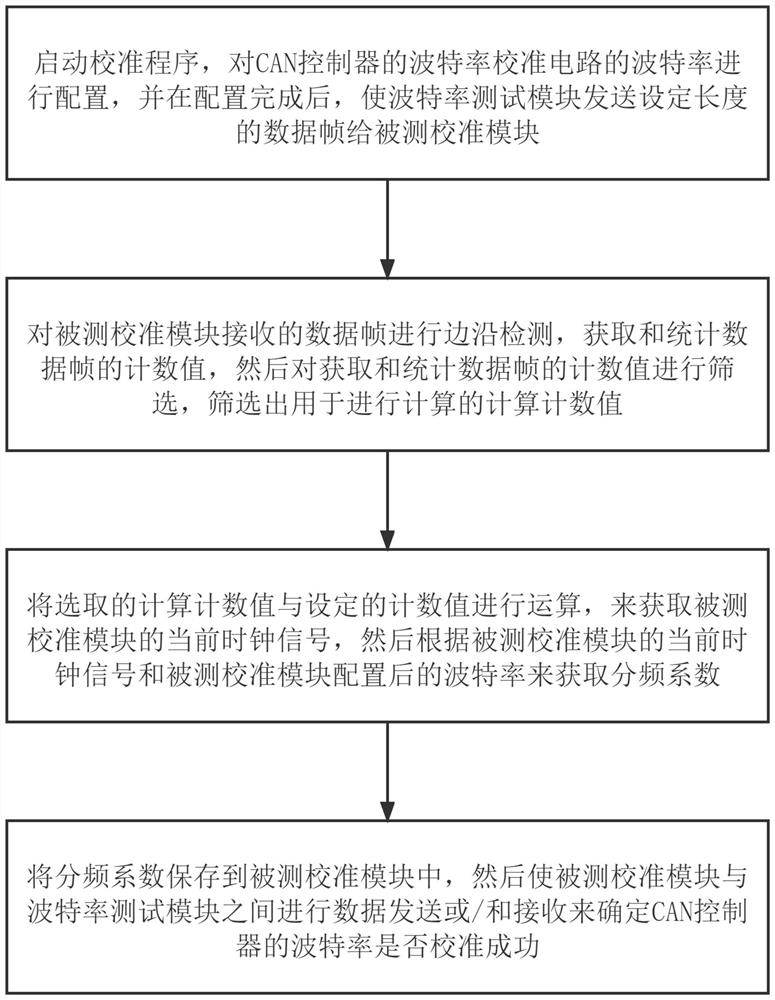
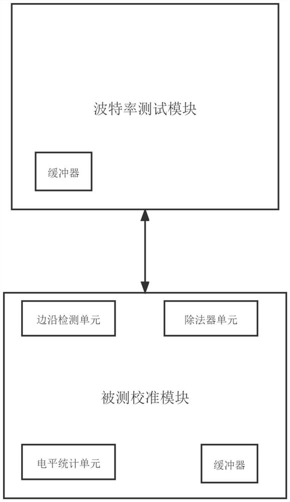
The invention discloses a baud rate calibration method and calibration circuit for a CAN controller, and the method comprises the steps: S1, starting a calibration program, carrying out the calibration, and enabling a calibration module to transmit a data frame with a set length to a tested calibration module; s2, carrying out edge detection on the data frame received by the detected calibration module, obtaining and counting a single-bit high level count value, and then screening out a single extra-high level value for calculation; s3, calculating the selected single extra-high level count value and the count value of the calibration module to obtain the actual frequency of the current clock signal of the tested calibration module, and calculating the calibrated Baud rate according to the actual frequency of the tested calibration module to obtain a frequency division coefficient; and S4, storing the frequency division coefficient in the tested calibration module, and then performing data transmission or / and receiving between the tested calibration module and the baud rate test module to determine whether the baud rate of the CAN controller is successfully calibrated.

Description

technical field [0001] The invention relates to the field of intelligent robots, in particular to a baud rate calibration method and a calibration circuit of a CAN controller. Background technique [0002] Because the CAN bus uses differential signals for data transmission, it has a strong anti-interference ability. At the same time, because it uses a non-destructive bus arbitration mechanism, even if different nodes send data to the CAN bus at the same time, there will be no data confusion. and communication errors, due to the various advantages of the CAN bus, the CAN bus control system is widely used in various types of automation equipment. [0003] In the CAN bus network, the devices or sensors of each node are often diverse. If you want to make the CAN bus communicate normally and stably, you must ensure that the baud rate error between the nodes is kept within the CAN bus. Accept range. Therefore, the baud rate between CAN bus nodes cannot have too large a frequency...

Claims


Application Information

Patent Timeline
Patent Type & Authority Applications(China)
IPC IPC(8): H04L12/40
CPCY02D30/50
Inventor 高桂何再生
Owner AMICRO SEMICON CORP
Learn More