Charging method, charging device, and electronic device

A technology of electronic equipment and charging method, which is applied in the direction of battery disconnection circuit, battery circuit device, current collector, etc., can solve the problem of fast decay speed of battery cycle life and so on

Active Publication Date: 2019-03-12
NINGDE AMPEREX TECH
View PDF4 Cites 9 Cited by
  • Summary
  • Abstract
  • Description
  • Claims
  • Application Information

AI Technical Summary

Problems solved by technology

[0004] The embodiment of the present invention provides a charging method, charging equipment and electronic equipment, which are used to solve the problem that the battery cycle life of the existing electronic equipment has a fast decay rate due to the fact that the battery is often in a fully charged state

Method used


Image

  • Charging method, charging device, and electronic device
  • Charging method, charging device, and electronic device
  • Charging method, charging device, and electronic device

Examples


Embodiment 1

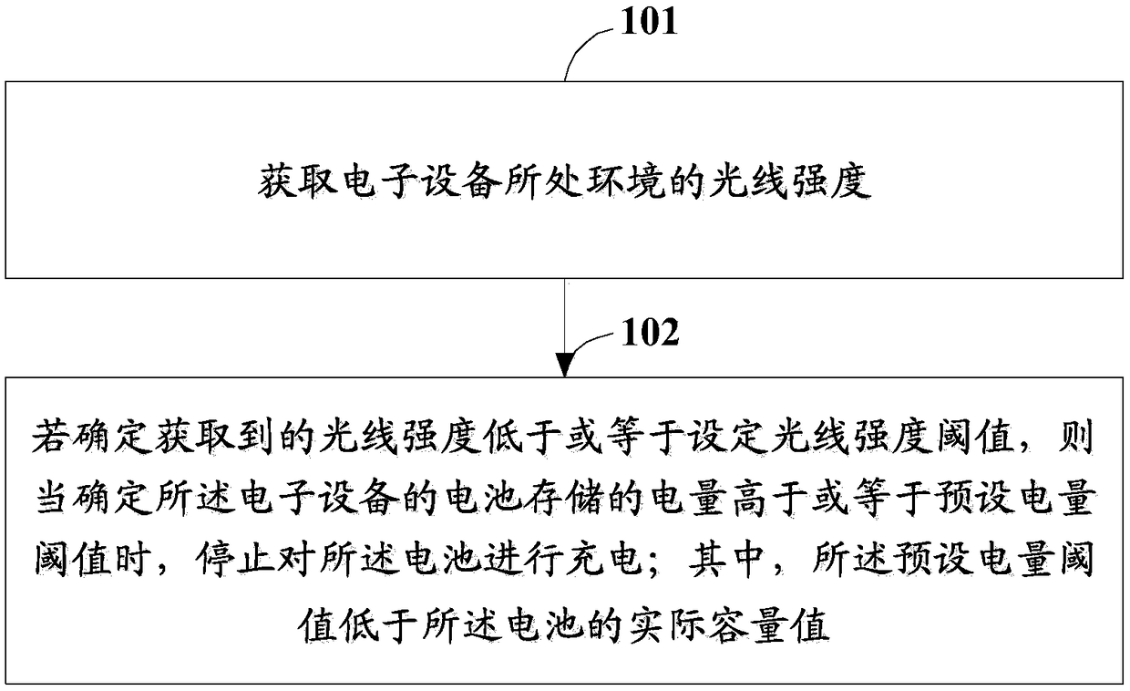
[0040] Embodiment 1 of the present invention provides a charging method, which is applied to the charging control of a battery installed in an electronic device, specifically as figure 1 As shown, it is a flow chart of the steps of the method described in Embodiment 1 of the present invention, and the method may include the following steps:

[0041] Step 101: Obtain the light intensity of the environment where the electronic device is located.

[0042] Optionally, the electronic device may be an electronic terminal such as a smart phone, a tablet computer, an e-reader, a smart watch, or a smart bracelet, which is not limited in this embodiment.

[0043] Also optionally, the implementation subject of the charging method may be a setting function module of the application processor of the electronic device, that is, the application processor of the electronic device may implement the charging method; the implementation of the charging method The main body may also be a speciall...

Embodiment 2

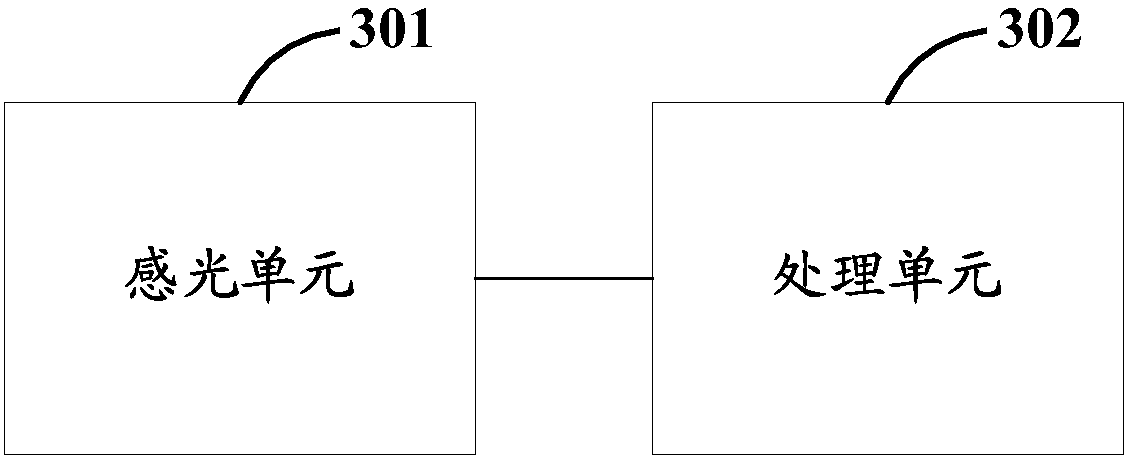
[0084] Based on the same inventive concept, Embodiment 2 of the present invention provides a charging device, which can be applied to control the charging of a battery installed in an electronic device. Specifically, such as image 3As shown, it is a schematic structural diagram of the device described in Embodiment 2 of the present invention, and the device may include:

[0085] a photosensitive unit 301, configured to acquire the light intensity of the environment where the electronic device is located;

[0086] The processing unit 302 is configured to stop charging the battery if it is determined that the acquired light intensity is lower than or equal to the set light intensity threshold, and when it is determined that the power stored in the battery is higher than or equal to the preset power threshold;

[0087] Wherein, the preset power threshold is lower than the actual capacity value of the battery.

[0088] Optionally, the processing unit 302 may be specifically con...

Embodiment 3

[0095] Embodiment 3 of the present invention provides an electronic device, such as Figure 4 As shown in , it is a schematic structural diagram of the electronic device described in the embodiment of the present invention. Specifically, the electronic device may be a desktop computer, a portable computer, a smart phone, a tablet computer, a personal digital assistant (Personal Digital Assistant, PDA) and the like. Specifically, by Figure 4 It can be seen that the electronic device described in the embodiment of the present invention may include a central processing unit 401 (Center Processing Unit, CPU), a memory 402, an input device 403, and an output device 404, etc., and the input device 403 may include a keyboard, a mouse, and / or a touch screen etc., the output device 404 may include a display device, such as a liquid crystal display (Liquid Crystal Display, LCD), a cathode ray tube (Cathode Ray Tube, CRT), and the like.

[0096] The memory 402 may include a read only ...


PUM


Abstract

The invention provides a charging method, a charging device, and an electronic device, and is applied to charging control of a battery arranged in the electronic device. The method includes steps: obtaining a light intensity of an environment in which the electronic device is located; and stopping charging of the battery if it is determined that the obtained light intensity is lower than or equalto a set light intensity threshold and it is determined that the capacity stored by the battery is higher than or equal to a preset capacity threshold, wherein the preset capacity threshold is lower than a practical capacity value of the battery. In other words, whether the current time for charging of the battery of the electronic device is night is determined through the obtained light intensityof the environment in which the electronic device is located, and if yes, the charging of the battery is stopped when the capacity stored by the battery of the electronic device is lower than the practical capacity value of the battery so that the acceleration of attenuation of the cycle life of the battery due to long-time full-charging state of the battery of the electronic device after charging at night is avoided, and the service lifetime of the battery is prolonged.

Description

technical field [0001] The invention relates to the technical field of charging, in particular to a charging method, charging equipment and electronic equipment. Background technique [0002] The batteries installed in electronic equipment are generally lithium-ion batteries. As the configuration of electronic equipment continues to improve, the demand for power and consumption continue to increase, the requirements for the life of lithium-ion batteries are also getting higher and higher. For example, dedicated to It is of great significance to increase the cycle life of lithium-ion batteries from 500 cycles to 800 cycles, 1000 cycles, and even 1500 cycles. [0003] The inventor found in the process of implementing the present invention that if the lithium-ion battery is often in a fully charged state during use (the electric quantity stored in the lithium-ion battery is equal to the actual capacity value of the battery), the cycle life of the lithium-ion battery will be acc...

Claims


Application Information

Patent Timeline
Patent Type & Authority Applications(China)
IPC IPC(8): H02J7/00
CPCH02J7/0031
Inventor 曾巧王可飞江静吴飞袁庆丰
Owner NINGDE AMPEREX TECH
Why Eureka
Try Eureka