
Positioning drilling system for I-beam and box beam

A technology of I-beams and box beams, which is applied in the direction of drilling molds for workpieces, etc., can solve the problems of not being able to meet batch production and low hole making precision, and achieve fast adjustment and alignment, high quality and precision, and reduce labor intensity Effect

Pending Publication Date: 2019-03-15
CHINA RAILWAY JIUJIANG BRIDGE ENG
View PDF5 Cites 2 Cited by
  • Summary
  • Abstract
  • Description
  • Claims
  • Application Information

AI Technical Summary

Problems solved by technology

[0003] The purpose of the present invention is to provide a positioning drilling system for I-beams and box girders, which solves the problems of low drilling precision and low drilling accuracy caused by the use of single rods in the existing building construction. Can not meet the problem of mass production and high-efficiency production

Method used


Image

  • Positioning drilling system for I-beam and box beam
  • Positioning drilling system for I-beam and box beam
  • Positioning drilling system for I-beam and box beam

Examples


Embodiment Construction

[0019] Below in conjunction with accompanying drawing, the present invention will be further described.

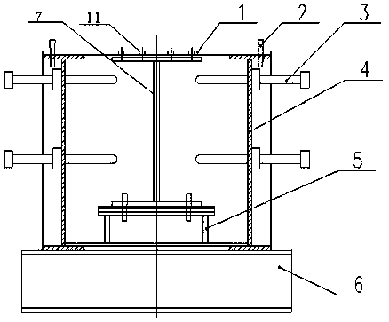
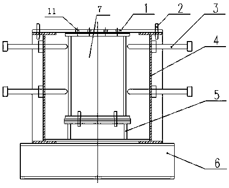
[0020] The system includes pad beams 6, such as Figure 1-Figure 8 As shown, the upper end of the pad beam 6 is provided with a height-adjusting pedestal 5, and the upper end of the height-adjusting pedestal 5 is provided with a workpiece 7, and the upper end of the pad beam 6 is located on both sides of the height-adjusting pedestal 5 and is provided with a tooling tire frame. 4. A plurality of horizontal adjustment screw rods 3 are provided on the tooling tire frame 4, and a drilling template 1 is provided on the upper end of the workpiece 7, and the two ends of the drilling template 1 are respectively fixed on the height adjustment pads 5 through positioning pins 2. The tooling tire frame 4 upper ends of side.

[0021] A group of holes 11 are arranged on the upper end of the workpiece 7 on the drilling template 1 .

[0022] The tooling tire frame 4 includes two longit...


PUM


Abstract

A positioning drilling system for an I-beam and a box beam, comprising a pad beam, wherein the upper end of the pad beam is provided with a height adjustment pad, the upper end of the height adjustment pad is provided with a workpiece, tooling bed-jigs are arranged at two sides of the height adjustment pad on the upper end of the pad beam and are provided with a plurality of lateral adjustment screw rods, the upper end of the workpiece is provided with a drilling mold plate, and both ends of the drilling mold plate are respectively fixed to the tooling bed-jigs at two sides of the height adjustment pad by positioning pins. The system can accurately locate and drill the I-beam and the box beam, ensure the accuracy of the workpiece hole group and greatly improve the efficiency, and is suitable for the factory manufacturing of batch I-beams or box beams.

Description

technical field [0001] The invention relates to a positioning drilling system for I-shaped beams and box-shaped beams. Background technique [0002] I-beams and box girders are often used in the field of building construction, but in the past, a single bar was used to drill holes with a small formwork, which was not accurate enough and could not meet the needs of batch and high-efficiency production. Contents of the invention [0003] The purpose of the present invention is to provide a positioning drilling system for I-beams and box girders, which solves the problems of low drilling precision and low drilling accuracy caused by the use of single rods in the existing building construction. Can not meet the problem of mass production and high-efficiency production. [0004] The technical solution adopted to achieve the above purpose is a positioning drilling system for I-beams and box beams, including a pad beam, the upper end of the pad beam is provided with a height-adju...

Claims


Application Information

Patent Timeline
Patent Type & Authority Applications(China)
IPC IPC(8): B23B47/28
CPCB23B47/28B23B2247/12
Inventor 付建辉朱东明王员根黄旭光余维杰马得利王中美
Owner CHINA RAILWAY JIUJIANG BRIDGE ENG
Learn More