
Robot constant-force polishing method

A robot and constant force technology, applied in grinding/polishing equipment, parts of grinding machine tools, manufacturing tools, etc., can solve the problems of robot scratches, poor surface consistency, etc., to reduce human errors, improve the quality of polished surfaces and Accuracy, the effect of reducing mutual influence

Active Publication Date: 2019-03-15
WUHAN UNIV OF TECH
View PDF5 Cites 3 Cited by
  • Summary
  • Abstract
  • Description
  • Claims
  • Application Information

AI Technical Summary

Problems solved by technology

[0004] The purpose of the present invention is to solve the problems of poor consistency of the traditional manual polishing surface and serious scratches in the robot polishing process, and provide a robot constant force polishing method imitating human hands

Method used


Image

  • Robot constant-force polishing method
  • Robot constant-force polishing method
  • Robot constant-force polishing method

Examples


example 1

[0036] Example 1: Robot constant force polishing method for flat surfaces

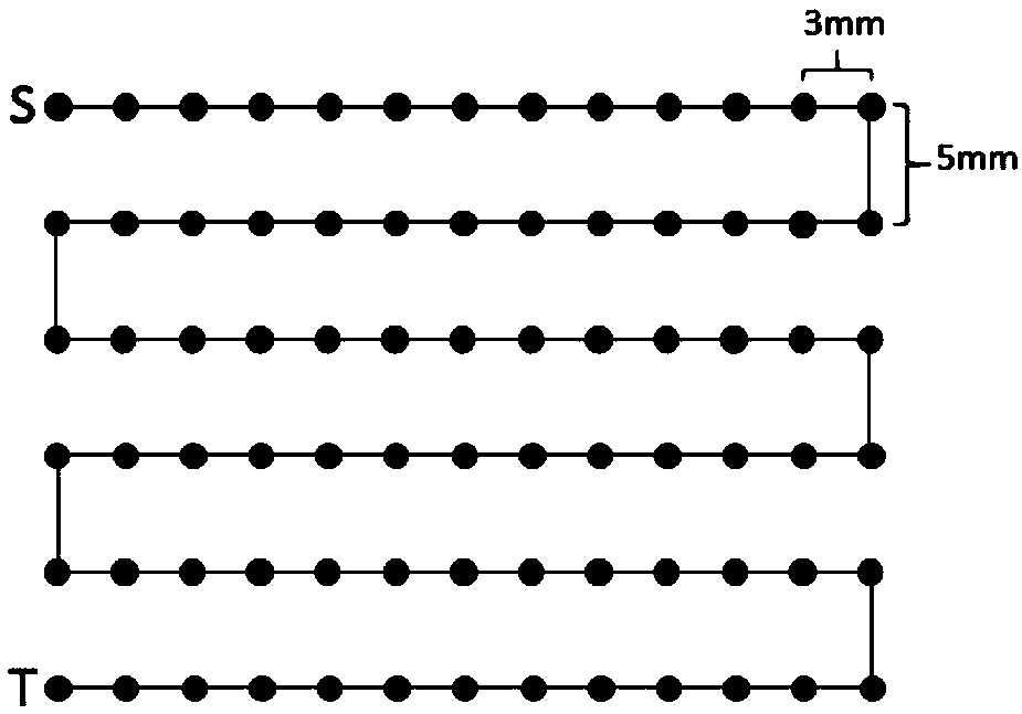
[0037] Step 1: Obtain the equation g(x, y, z) of the processed surface of the workpiece, such as figure 1 The plane equation shown is g(x,y,z) where (0<=x<=36, y=0,0<=z<=25), y is the direction perpendicular to the paper surface, z is the paper The up-down direction of the plane, x is the left-right direction of the paper plane;

[0038] Step 2: Set the start and end points of the processing range as S(0,0,25), T(0,0,0);

[0039] Step 3: Generate a reference point G on the i-th row and j-column on the processing surface g(x, y, z) in a row-scanning manner with a row spacing of D=5mm and a column spacing of L=3mm ij (X ij ,Y ij ,Z ij );

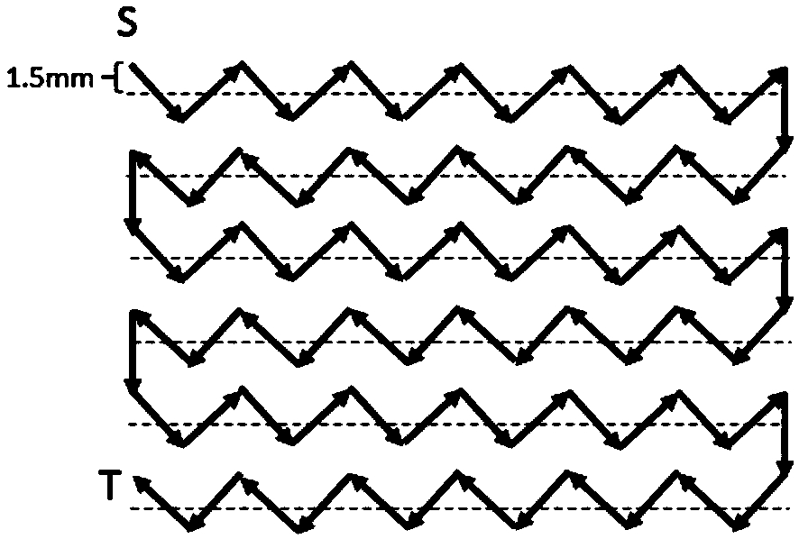
[0040] Step 4: Set the offset range △G(0,0,±1.5), offset the reference point of the workpiece surface to be processed to obtain the path control point S k =G ij +△G i , k=(i-1)+j, k is the ordinal number of the path control point, in the adjacent path control ...

example 2

[0043] Example 2: Robot constant force polishing method for curved surfaces

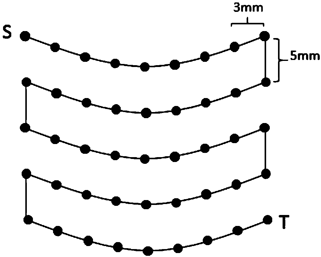
[0044] Step 1: Obtain the equation g(x, y, z) of the processed surface of the workpiece, such as image 3 The plane equation of the arc shown is g(x, y, z) where (x2+y2=122,,0<=z<=25);

[0045] Step 2: Set the start and end points of the processing range as S(-12,0,20), T(12,0,0);

[0046]Step 3: Generate a reference point G on the i-th row and j-column on the processing surface g(x, y, z) in a row-scanning manner with a row spacing of D=5mm and a column spacing of L=3mm ij (X ij ,Y ij ,Z ij );

[0047] Step 4: Set the offset range △G(0,0,±1), offset the reference point of the workpiece surface to be processed to obtain the path control point S k =G ij +△G i , k=(i-1)+j, k is the ordinal number of the path control point, in the adjacent path control point S k The interpolation algorithm is used to form the robot polishing trajectory, such as Figure 4 Polishing path shown;

[0048] Step 5:...


PUM


Abstract

The invention discloses a robot constant-force polishing method. The polishing method comprises the following steps of: firstly guiding a to-be-polished part model into robot software; picking pointson a to-be-polished surface; setting the intervals and line spaces among the picked points; subsequently randomly generating offset for the points so as to offset the points to finally generate a route; and setting the magnitude and direction of force to implement constant-polishing for the surface of a part. The polishing method disclosed by the invention can prevent the problem about serious scratches on the polished surface, can guarantees the consistency of the overall polished surface and can effectively improve the surface roughness of a workpiece.

Description

technical field [0001] The invention relates to the field of mechanical processing, and relates to a polishing method of a robot, in particular to a constant force polishing method of a robot. Background technique [0002] Polishing refers to grinding the surface of the workpiece to make it brighter. The initial polishing usually does not measure and does not change the size of the part. The polishing method uses soft tools such as wool felt and wire wheels for mechanical polishing. With the continuous development of polishing technology, polishing can also achieve quantitative removal within a certain range. At the same time, polishing methods have also developed into different types such as physics, chemistry, electrolysis, and ultrasonic waves. The surface quality of the polished parts is higher and the finish is higher, which can remove the metamorphic layer and stress layer left by milling and other processing, thereby improving the life and performance of the parts. ...

Claims


Application Information

Patent Timeline
Patent Type & Authority Applications(China)
IPC IPC(8): B24B1/00B24B51/00
CPCB24B1/00B24B51/00
Inventor 吴超群曹诗宇
Owner WUHAN UNIV OF TECH
Learn More