Helicopter main paddle assembly and helicopter

A helicopter and assembly technology, applied in the field of helicopters, can solve the problems of damaged steering gear, complex force conditions, breakage and failure of anti-rotation pins, etc., and achieve the effect of improving stability and reducing the risk of failure

Pending Publication Date: 2019-03-15
珠海隆华直升机科技有限公司
View PDF6 Cites 0 Cited by
  • Summary
  • Abstract
  • Description
  • Claims
  • Application Information

AI Technical Summary

Problems solved by technology

[0004] The patent with the publication number CN104369859A discloses a swash plate device and control method for a UAV piloted helicopter. The rotating cup of the swash plate rotates directly relative to the main shaft. Larger torque and tension, the force situation is complex, easy to break and cause damage, and once the rotating cup is damaged, the matching relationship between the rotating cup and the fixed cup will be destroyed, at this time the fixed cup is prone to movement or vibration intensifies The rigid collision between the anti-rotation pin and the pin groove, once the anti-rotation pin comes out of the pin groove and the cooperation between the two is released, the rotation of the rotating cup will transmit the torque to the output end of the action rod and the steering gear through the fixed cup, further damaging the rudder Machine; the fixed cup body is controlled by a set of anti-rotation guide rails and anti-rotation pins. Due to the matching error between the anti-rotation pin and the pin groove, the anti-rotation pin is prone to slight displacement in the pin groove. This structure is easy to cause the fixed cup body The rigid collision with the anti-rotation pin will easily lead to the deformation of the fixed cup and the failure of the fracture of the anti-rotation pin when the force is too large. The anti-rotation pin will slide and swing frequently in the pin groove with the fixed cup on the main shaft Reciprocating sliding, especially when the fixed cup body swings, the friction surface between the detent pin and the pin groove will change, and there will be complex friction stress on the surface of the detent pin and the pin groove, resulting in greater wear on the surface, and due to friction The change of the surface is easy to produce sharp edges and corners, and the sharp edges and corners will cause large scratches on the surface of the parts in contact with it. In such a vicious cycle, long-term wear will increase the gap between the detent pin and the pin groove. The rigid collision between the two reduces the structural strength of the anti-rotation pin at the same time, which further increases the risk of fracture of the anti-rotation pin; the movement of the longitudinal and lateral periodic distances of the swash plate interferes with each other, causing the fixed and rotating cups, etc. The components are unevenly stressed, the fixed cup body and the rotating cup body are easily damaged, and the control accuracy is low

Method used


Image

  • Helicopter main paddle assembly and helicopter
  • Helicopter main paddle assembly and helicopter
  • Helicopter main paddle assembly and helicopter

Examples


Embodiment Construction

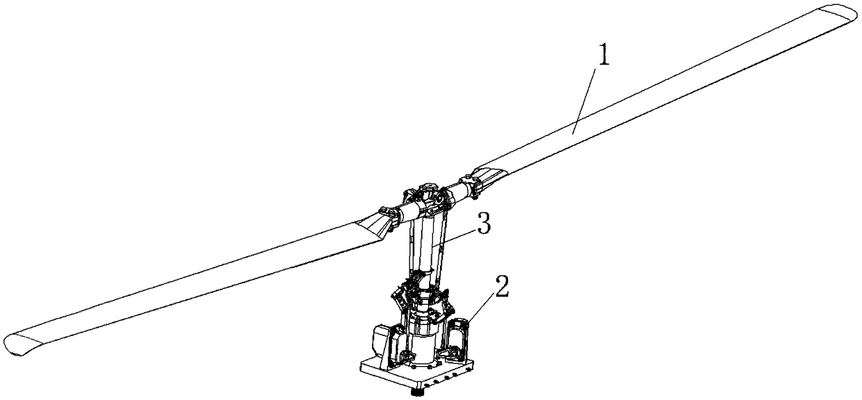
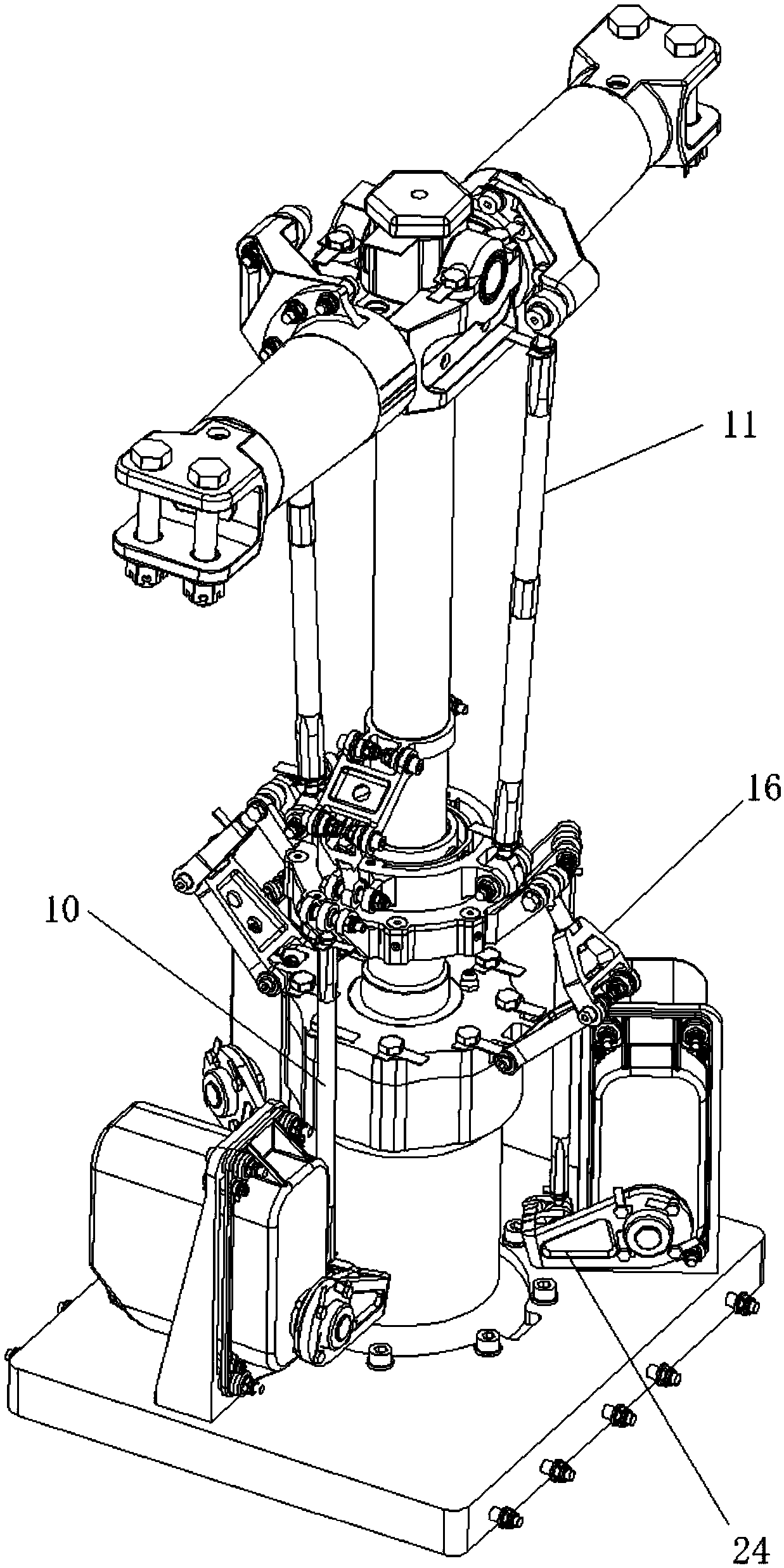
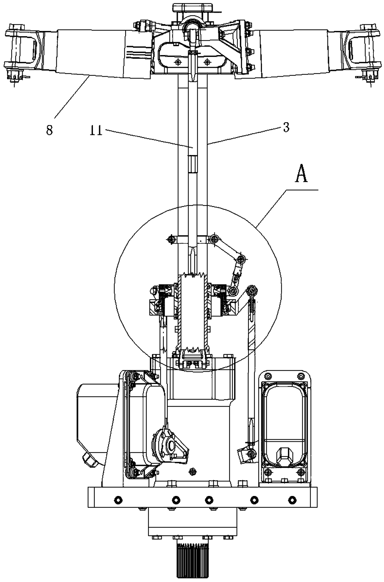
[0033] figure 1 It is a schematic diagram of the structure of the isometric side of the present invention; figure 2 It is a schematic diagram of the structure of the isometric side of the present invention (hiding the main blade); image 3 It is a schematic diagram of the structure of the present invention; Figure 4 for image 3 Schematic diagram of the right-view structure of ; Figure 5 for image 3 Schematic diagram of the enlarged structure at point A; Image 6 Schematic diagram of the swing hinge connection structure; Figure 7 It is a schematic diagram of the universal joint structure;

[0034] As shown in the figure: the helicopter main propeller assembly of this embodiment includes the main propeller, the main drive device for driving the main propeller to rotate, the swash plate assembly for making the blades of the main propeller realize independent or partially independent pitch change, and the The variable pitch drive device 2 for driving the swash plate a...


PUM


Abstract

The invention discloses a helicopter main paddle assembly and a helicopter. The helicopter main paddle assembly comprises a main paddle, a main driving device for driving the main paddle to rotate, aninclined disk assembly for implementing an independent or partially independent pitch change of blades of the main paddle, and a pitch change driving device for driving the inclined disk assembly, wherein the inclined disk assembly comprises an inclined disk; the inclined disk is fixedly connected to an universal joint and can rotate along with the universal joint; the universal joint is connected with an outer circle of an inner ring sleeve; and a rotor wing shaft of the main paddle is sleeved with the inner ring sleeve in an axially sliding manner. According to the invention, the independence of the pitch change of a plurality of blades of the main paddle can be realized by the inclination characteristics of the inclined disk assembly, and the mutual influence of the blades when the pitch is changed is reduced; the inner ring sleeve is only used for achieving the function of axial sliding; the inclined disk is used for bearing torque and tilting swing; by adopting the structure, theforce on the inner ring sleeve and the force on the inclined disk are changed, and the risks of rupture and damage of the inner ring sleeve and the inclined disk are reduced.

Description

technical field [0001] The invention belongs to the technical field of helicopters, in particular to a helicopter main propeller assembly and a helicopter. Background technique [0002] Helicopter rotor system is a complex mechanical structure. For the rotor system of medium and large helicopters, the paddle body is arranged on the rotor shaft, and the joint between the paddle body and the rotor shaft needs to be provided with shimmy hinges, flapping hinges and variable pitch hinges. A hinge structure enables each blade to wave, swing and change the pitch; when changing the pitch, the drive system drives the variable pitch hinge to adjust the pitch. The adjustment of the existing pitch usually uses a steering gear to drive the swash plate and Drive the variable pitch hinge by driving the pitch variable rod through the swash plate, [0003] At present, there are two forms of control of the helicopter rotary tilting system: single-channel independent control and multi-channel...

Claims


Application Information

Patent Timeline
Patent Type & Authority Applications(China)
IPC IPC(8): B64C11/32
CPCB64C11/32
Inventor 张伟谢泽锋王曦田陈劲舟杨海生屈宗源高洪军
Owner 珠海隆华直升机科技有限公司
Why Eureka
Try Eureka