
Noise-reducing air flue shell and nitrogen and oxygen separating device employing same

A shell and air duct technology, which is applied in the field of noise-reducing air duct shells, can solve problems such as affecting sleep, high noise, and complicated production and assembly, and achieve the effect of facilitating mass production, obvious economic benefits, and simple and delicate structure

Pending Publication Date: 2019-03-15
JIANGSU YUYUE MEDICAL EQUIP&SUPPLY CO LTD +4
View PDF8 Cites 2 Cited by
  • Summary
  • Abstract
  • Description
  • Claims
  • Application Information

AI Technical Summary

Problems solved by technology

[0003] At present, the oxygen generator system on the market has a relatively complex structure, complex production and assembly, low efficiency, high cost, and relatively high noise.
Industry standard "YY0732-2009 Safety Requirements for Medical Oxygen Concentrators" "4.6 Vibration and noise, under normal use conditions, the maximum A-weighted sound pressure level (stable value or peak value) of the oxygen concentrator should not exceed 60dB", the market The noise of the oxygen concentrator is basically about 50dB. When it is placed indoors at night, the noise during work will make people irritable, affect sleep, and seriously affect the effect of oxygen therapy. The urgent need to be competitive
[0004] The noise sources of the oxygen generator mainly include intake noise, exhaust noise, noise when the switching valve is switched, and compressor noise. At present, the oxygen generator mainly uses porous sound-absorbing materials to reduce noise, and the sound-absorbing materials are fixed in the air flow channel. Arranged on the inner wall or in a certain way in the pipeline to form a damping muffler, the damping muffler has a good noise reduction effect on medium and high frequencies, but has a poor noise reduction effect on low frequencies

Method used


Image

  • Noise-reducing air flue shell and nitrogen and oxygen separating device employing same
  • Noise-reducing air flue shell and nitrogen and oxygen separating device employing same
  • Noise-reducing air flue shell and nitrogen and oxygen separating device employing same

Examples


Embodiment Construction

[0034] The present invention will be further described below in conjunction with the accompanying drawings and embodiments.

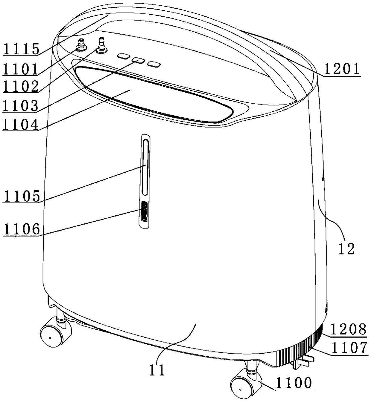
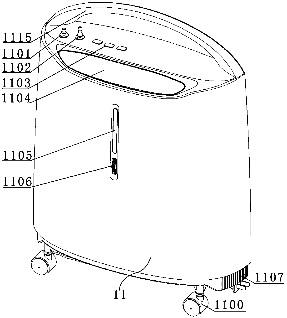
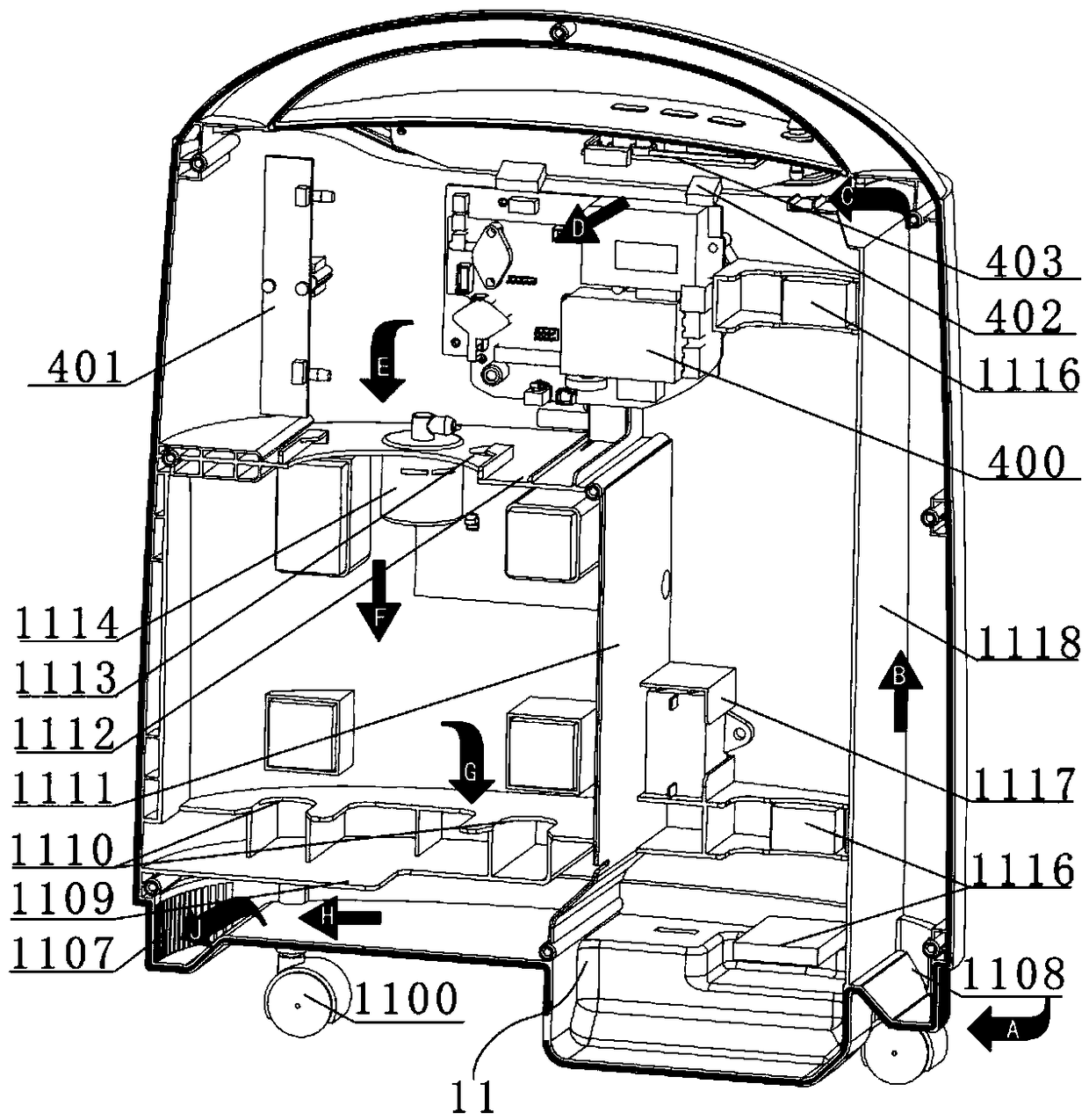
[0035] refer to Figure 1 to Figure 7 As shown, the noise reduction air duct housing of this embodiment only includes the first sub-housing 11 and the second sub-housing 12, and the first sub-housing 11 and the second sub-housing 12 are located on the front and rear sides of the housing respectively. , the shapes of the two are basically symmetrically arranged, and the two sub-housings are assembled to form a complete housing (the two sub-housings can be fixedly connected by means including but not limited to socket structures, buckle structures, screws or gluing) ), the first sub-housing 11 and the second sub-housing 12 are assembled to form an oxygen-generating component accommodating cavity inside, and all oxygen-generating components are placed in the accommodating cavity inside the housing.

[0036] The inner walls of the first sub-housing 11 and ...


PUM


Abstract

The invention discloses a noise-reducing air flue shell and a nitrogen and oxygen separating device employing the same. The noise-reducing air flue shell comprises a first branch shell and a second branch shell. The first branch shell and the second branch shell are spliced to form an integral shell. An accommodating cavity for the placement of an oxygen making assembly is formed in the shell. Pairs of partition plates are correspondingly arranged on the inner walls of the two branch shells in a matched manner to divide the accommodating cavity into a plurality of communicating cavities. An air flow wind channel is formed by combining the communicating cavities with the oxygen making assembly. The noise-reducing air flue shell can dissipate head in the shell effectively and prolongs air entering the air flow wind channel of the shell, so that noises from noise sources such as an inner air flow, a compressor, a switch valve and a silencer in the shell can be isolated, reduced and absorbed effectively.

Description

technical field [0001] The invention relates to a nitrogen-oxygen separation device, in particular to a noise reduction air duct housing of the nitrogen-oxygen separation device. Background technique [0002] The oxygen and nitrogen separation device is a device that separates nitrogen and oxygen in the air. It is divided into nitrogen generators and oxygen generators. The oxygen generator is a device that provides high-concentration oxygen that can be used for human breathing. With the improvement of people's living standards and the progress of society, people have more awareness of oxygen generators, and the demand for use is also increasing. They have been widely used in hospitals and homes, and are also used in industries such as aquaculture. Oxygen concentrators are used for oxygen therapy for people suffering from respiratory diseases, cardiovascular system diseases, cerebrovascular diseases, altitude sickness and altitude sickness, for middle-aged and elderly infirm,...

Claims


Application Information

Patent Timeline
Patent Type & Authority Applications(China)
IPC IPC(8): C01B13/02C01B21/04
CPCC01B13/0259C01B21/045
Inventor 张丽琴毛坚强蔡林泉
Owner JIANGSU YUYUE MEDICAL EQUIP&SUPPLY CO LTD
Learn More