
High-low-cycle complex fatigue test clamp of turbine joggle joint structure

A fatigue test and fixture technology, which is applied in the testing of machine/structural parts, testing of mechanical parts, measuring devices, etc., can solve the problems of easy slippage of blades and uneven stress distribution, and achieve rich high-low cycle composite fatigue tests and tests. Wide range, the effect of improving the carrying capacity

Active Publication Date: 2019-03-15
BEIHANG UNIV
View PDF8 Cites 12 Cited by
  • Summary
  • Abstract
  • Description
  • Claims
  • Application Information

AI Technical Summary

Problems solved by technology

[0006] The technical problem to be solved by the present invention is to provide a high-low-cycle composite fatigue test fixture for a turbine tenon joint structure, which overcomes the difficulty that the turbine tenon joint structure is simultaneously loaded with a lateral high-cycle load under the condition of a low-cycle heavy load, and the blade directly The clamping is prone to slippage and uneven stress distribution, which can meet the effective and stable application of various loads, and can carry out the high-low cycle composite fatigue test of the turbine tenon joint

Method used


Image

  • High-low-cycle complex fatigue test clamp of turbine joggle joint structure
  • High-low-cycle complex fatigue test clamp of turbine joggle joint structure
  • High-low-cycle complex fatigue test clamp of turbine joggle joint structure

Examples


Embodiment Construction

[0021] The present invention will be described in detail below in conjunction with the accompanying drawings and embodiments.

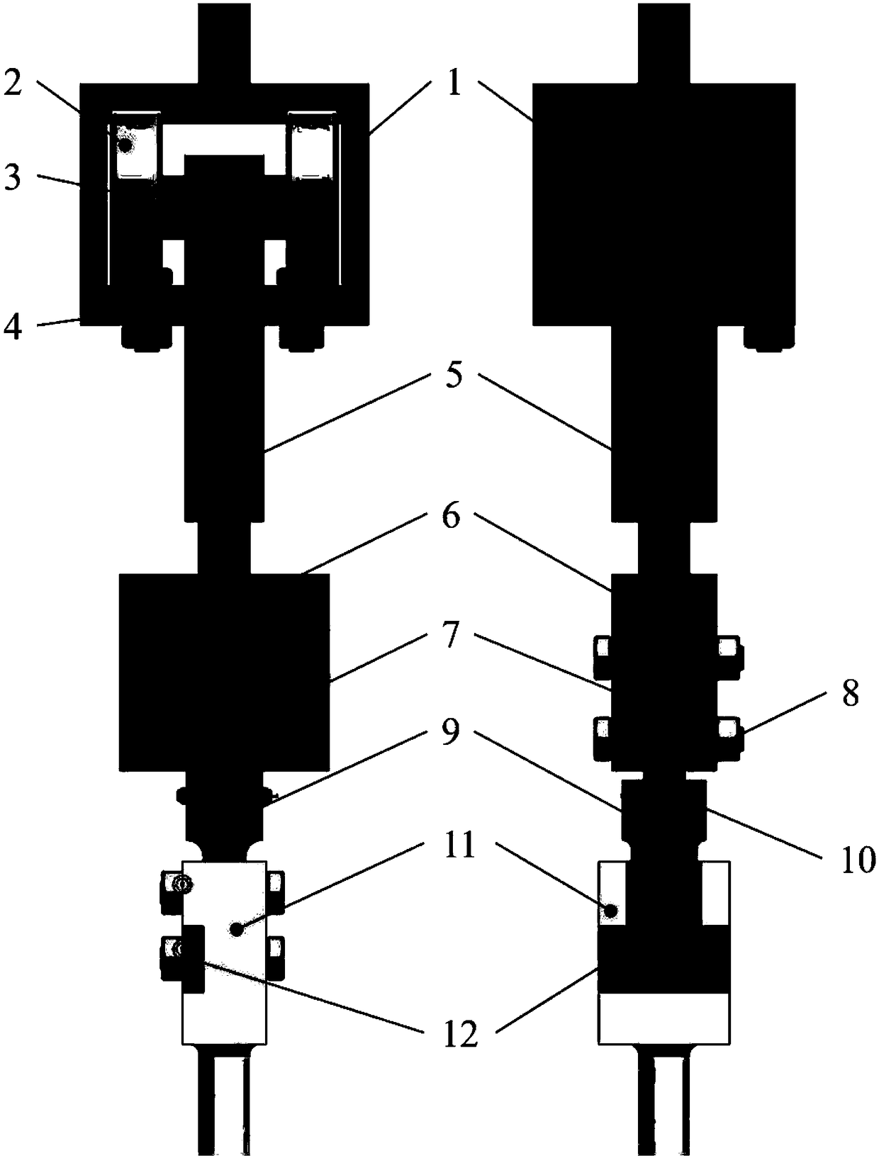
[0022] Such as figure 1 As shown, the present invention is mainly designed for the high-low cycle composite fatigue test fixture suitable for the turbine tenon joint structure, so as to realize the simultaneous testing of the turbine tenon joint structure with the longitudinal large strain low cycle vibration load, the transverse high cycle vibration load and the thermal load. load.

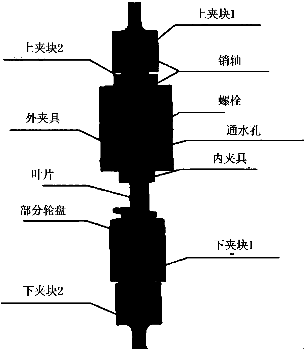
[0023] In the actual test, the structure of the whole set of fixtures is as follows: figure 1 As shown, it is divided into three parts: tenon clamping system composed of tenon fixture 6, compression block 7, tenon test piece 8; tenon and groove fixture 11, small compression block 12, tenon and groove test piece 9 Groove clamping system; a loading system composed of bearing installation box 1, ball bearing 2, transmission shaft 3, limit connection block 4, and force t...


PUM


Abstract

The invention relates to a high-low-cycle complex fatigue test clamp of an aero-engine turbine joggle joint structure. A fatigue machine clamps the lower end of a mortise clamp and fixes a mortise test piece through bolts; the mortise test piece is connected with a tenon test piece through tenon teeth and limited to slide in the mortise direction of the mortise through a limiting baffle; a tenon clamp clamps a tenon test piece clamping part through a double-wedged surface; the upper portion of the tenon clamp is connected with a force transmission pull rod through threads; three threaded holesare formed in the force transmission pull rod, high-cycle vibration excitation rods are screwed in the threaded holes, and the upper portion of the force transmission pull rod is in clearance fit with a roller transmission shaft through a shaft hole structure; the two ends of the roller transmission shaft are symmetrically provided with a pair of ball bearings to form a roller structure, the rollers move along two guide grooves in an installation box, and the constraint of the high-cycle load application direction is released; the top end of the installation box is clamped by the fatigue machine; a low-cycle load is applied by the fatigue machine, the excitation rods are externally connected with a vibration exciter to apply a high-cycle load, and the joggle joint position is externally connected with an electric induction heating copper coil to apply a heat load.

Description

technical field [0001] The invention belongs to the technical field of aerospace engines, and in particular relates to a high-low cycle composite fatigue test fixture with a turbine tenon joint structure. Background technique [0002] Aeroengine is an extreme product. Engine turbine blades and turbine disks work under complex load environments such as high temperature, high pressure, and high speed. The high-low cycle composite fatigue failure of the turbine tenon joint structure is the main failure mode of the tenon joint structure. In order to conduct in-depth research on the high-low cycle composite fatigue life of the tenon joint structure, a large number of composite fatigue tests on the tenon joint structure of the turbine are required, and the experimental research on the tenon joint structure of the turbine blades of the turboshaft engine is also a crucial task. Due to the small size of turboshaft engine turbine blades, usually less than 70 mm, and complex profiles, ...

Claims


Application Information

Patent Timeline
Patent Type & Authority Applications(China)
IPC IPC(8): G01M13/00
CPCG01M13/00
Inventor 胡殿印王荣桥鄢林曲震毛建兴
Owner BEIHANG UNIV
Learn More