
Inertia error correction method

An error correction and inertial group technology, which is applied in the field of synthetic aperture radar, can solve the problems of increasing sources of inertial group errors and failure to correct inertial group errors, and achieve the effects of improving accuracy, solving ranging errors, and improving imaging quality

Active Publication Date: 2019-03-15
THE GENERAL DESIGNING INST OF HUBEI SPACE TECH ACAD
View PDF10 Cites 4 Cited by
  • Summary
  • Abstract
  • Description
  • Claims
  • Application Information

AI Technical Summary

Problems solved by technology

In the bistatic SAR system, due to the separation of the transmitting and receiving platforms, the sources of inertial group errors increase. At present, there is no complete analysis method or system to correct the inertial group errors.

Method used


Image

  • Inertia error correction method
  • Inertia error correction method
  • Inertia error correction method

Examples


Embodiment Construction

[0045] The present invention will be described in further detail below in conjunction with the accompanying drawings and embodiments.

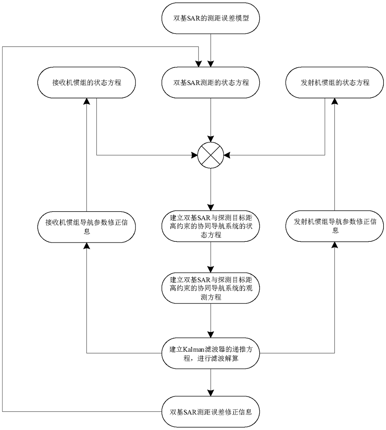
[0046] see figure 1 with figure 2 As shown, the embodiment of the present invention provides an inertial error correction method for error correction of the navigation parameters of the bistatic SAR, the transmitter inertial set, and the receiver inertial set, including the following steps:

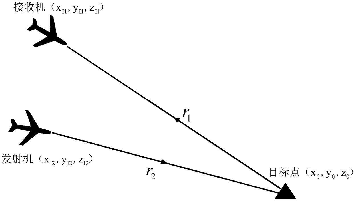
[0047] The ranging error model of bistatic SAR is established by taking the clock error of the receiver and the transmitter to be equivalent to the error in the distance;

[0048] Based on the ranging error model of bistatic SAR, the state equation of bistatic SAR ranging is established;

[0049] Establish the state equations of the receiver inertial group and the transmitter inertial group;

[0050] Establish the state equation of the cooperative navigation system based on bistatic SAR and detection target distance constraints;

[0051]Establish the...


PUM


Abstract

The invention discloses an inertia error correction method, and relates to the technical field of synthetic aperture radars. The inertia error correction method includes the steps that a distance measuring error model of a bistatic SAR is built; a state equation of bistatic SAR distance measurement is built; state equations of a receiver inertia unit and a transmitter inertia unit are built; a state equation of a collaborative navigation system based on the bistatic SAR and detection target distance constraint is built; an observation equation of the collaborative navigation system based on the bistatic SAR and detection target distance constraint is built; a recursion formula of a discrete Kalman filter is built, and Kalman filtering calculation is conducted; distance measuring error correction information of the bistatic SAR, navigation parameter correction information of the receiver inertia unit and navigation parameter correction information of the transmitter inertia unit are fedback to navigation calculation, and navigation parameters are corrected. By adopting the inertia error correction method, through the collaborative navigation system composed of the bistatic SAR, thereceiver inertia unit and the transmitter inertia unit, the precision of error estimation of the receiver inertia unit and the transmitter inertia unit can be improved.

Description

technical field [0001] The invention relates to the technical field of synthetic aperture radar, in particular to an inertial set error correction method. Background technique [0002] The bistatic SAR system refers to the synthetic aperture radar system in which the receiver and the transmitter are installed on different platforms, and the receiver and the transmitter can have different spatial positions and movement speeds. The transmitter transmits the chirp signal to the observation area, and the receiver receives the ground echo signal and performs imaging processing. Bistatic SAR has many outstanding advantages due to the separation of transceivers. It can obtain the non-backscatter information of the target, and has the characteristics of long range, concealment and strong anti-interference. Bistatic SAR can provide high-resolution images of the observation area all day and all day long. Therefore, bistatic SAR, as a new means of space-to-earth observation, is widely...

Claims


Application Information

Patent Timeline
IPC IPC(8): G01S13/90
Inventor 杨凯新王春联吴丰阳胡奇罗雪平沈志陈术涛闫士杰蔡昔
Owner THE GENERAL DESIGNING INST OF HUBEI SPACE TECH ACAD
Learn More