Positioning assembly for a back support of a mirror of an optical remote sensor

An optical remote sensor and mirror technology, applied in the field of optical remote sensors, can solve the problems of fatigue damage of supports and long duration of grinding process, and achieve the effect of avoiding fatigue damage

Inactive Publication Date: 2019-03-15
CHANGCHUN INST OF OPTICS FINE MECHANICS & PHYSICS CHINESE ACAD OF SCI
View PDF5 Cites 2 Cited by
  • Summary
  • Abstract
  • Description
  • Claims
  • Application Information

AI Technical Summary

Problems solved by technology

However, for a flexible support, it is subjected to a periodic alternating stress, and the grinding process generally lasts for a long time, and the support may have fatigue damage or near fatigue damage.

Method used


Image

  • Positioning assembly for a back support of a mirror of an optical remote sensor
  • Positioning assembly for a back support of a mirror of an optical remote sensor
  • Positioning assembly for a back support of a mirror of an optical remote sensor

Examples


Embodiment Construction

[0025] The following will clearly and completely describe the technical solutions in the embodiments of the present invention with reference to the accompanying drawings in the embodiments of the present invention. Obviously, the described embodiments are only some, not all, embodiments of the present invention. Based on the embodiments of the present invention, all other embodiments obtained by persons of ordinary skill in the art without making creative efforts belong to the protection scope of the present invention.

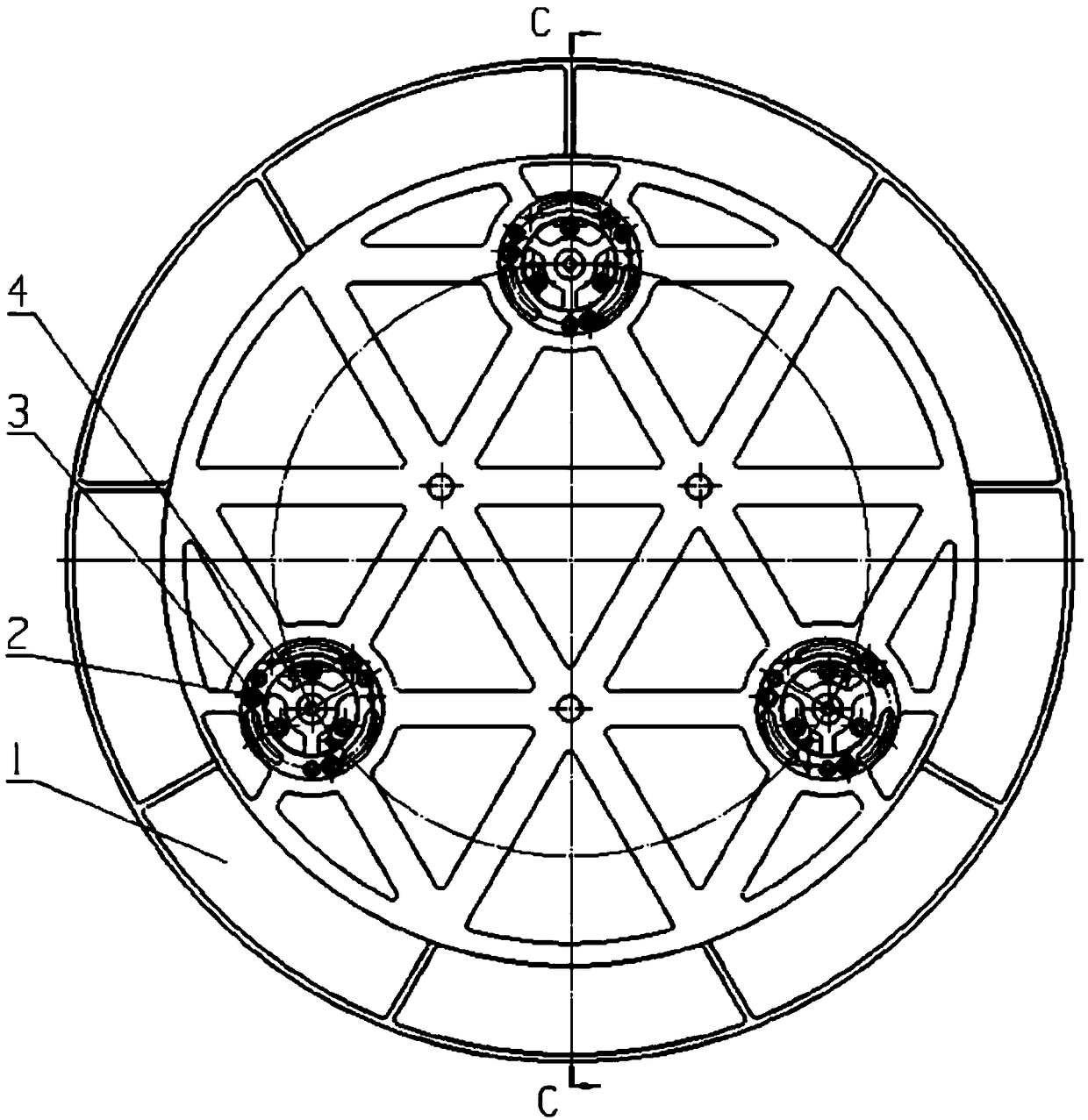
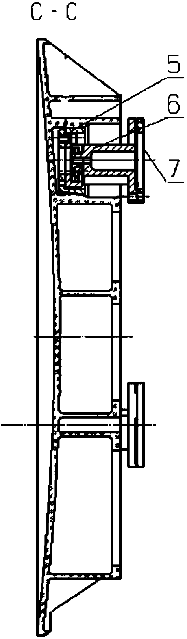
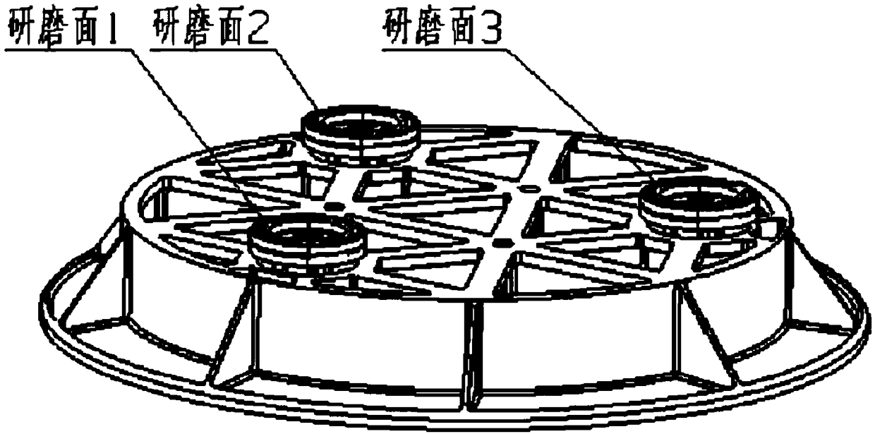
[0026] see Figure 4 and Figure 5 , the present invention provides a positioning structure 100 for the back support of the optical remote sensor mirror assembly, which is applied to the positioning of the back support of the optical remote sensor mirror assembly 200 during grinding. The optical remote sensor mirror assembly 200 includes a mirror body 1, three sets of flexible supports distributed on the circumference with the central axis of the mirror body ...


PUM


Abstract

The invention relates to a positioning assembly for a back support of a mirror of an optical remote sensor, which comprises a substrate; a first fixing component arranged on the substrate and used forfixing the mirror of the optical remote sensor; a bearing component which comprises a bearing piece arranged on the substrate and a second fixing component arranged on the bearing piece; the bearingpiece is used for bearing a contact pad of the mirror of the optical remote sensor, and the second fixing component is used for fixing the contact piece on the bearing piece. According to the invention, the mirror body and the contact pad are relatively fixed through the first fixing component and the bearing component; when grinding is carried out, the grinding force directly acts on the end faceof the contact pad at the back of the main mirror component and is directly transmitted to the substrate through the bearing component, the back support piece does not bear alternating stress so as to avoid fatigue damage, and meanwhile, the grinding force when grinding the end face of the contact pad can be greatly improved so as to improve the grinding efficiency of the coplanarity grinding ofa flexible end face.

Description

technical field [0001] The invention relates to the technical field of optical remote sensors, in particular to a positioning assembly for a back support of a mirror of an optical remote sensor. Background technique [0002] The application of space optical remote sensors in the fields of earth observation and space exploration has important scientific and economic significance. Mirror components in remote sensors are the most important components in the entire optical system, and their surface shape accuracy is directly related to the image quality of the entire remote sensor. Due to the large size of the mirror surface, under the action of comprehensive factors such as gravity load, temperature load and assembly error of the mirror assembly, the mirror surface often produces serious deformation. In order to reduce the sensitivity of the surface shape accuracy of the mirror assembly to the assembly error and temperature load The support structure of the mirror assembly gen...

Claims


Application Information

Patent Timeline
Patent Type & Authority Applications(China)
IPC IPC(8): G02B7/182
CPCG02B7/182
Inventor 王克军董吉洪王晓宇周平伟姜萍
Owner CHANGCHUN INST OF OPTICS FINE MECHANICS & PHYSICS CHINESE ACAD OF SCI
Why Eureka
Try Eureka