Numerically-controlled machine tool coolant filtering device

A filtering device and technology of CNC machine tools, which are applied in metal processing machinery parts, maintenance and safety accessories, metal processing equipment, etc., can solve problems such as waste of resources, easy blockage of drain pipes, and inability to use coolant directly, so as to improve circulation Good utilization rate and filtering effect

Active Publication Date: 2019-03-19
东莞市蓝拓数控机床有限公司
View PDF6 Cites 32 Cited by
  • Summary
  • Abstract
  • Description
  • Claims
  • Application Information

AI Technical Summary

Problems solved by technology

Generally divided into metal cutting machine tools, forging machine tools and woodworking machine tools, etc. During the processing of iron parts, various machine tools used in machining workshops will generate a large amount of iron filings, which will remain in the machining coolant In the process of machine tool equipment, a large amount of dust, solid particle pollutants and oth

Method used


Image

  • Numerically-controlled machine tool coolant filtering device
  • Numerically-controlled machine tool coolant filtering device
  • Numerically-controlled machine tool coolant filtering device

Examples


specific Embodiment approach 1

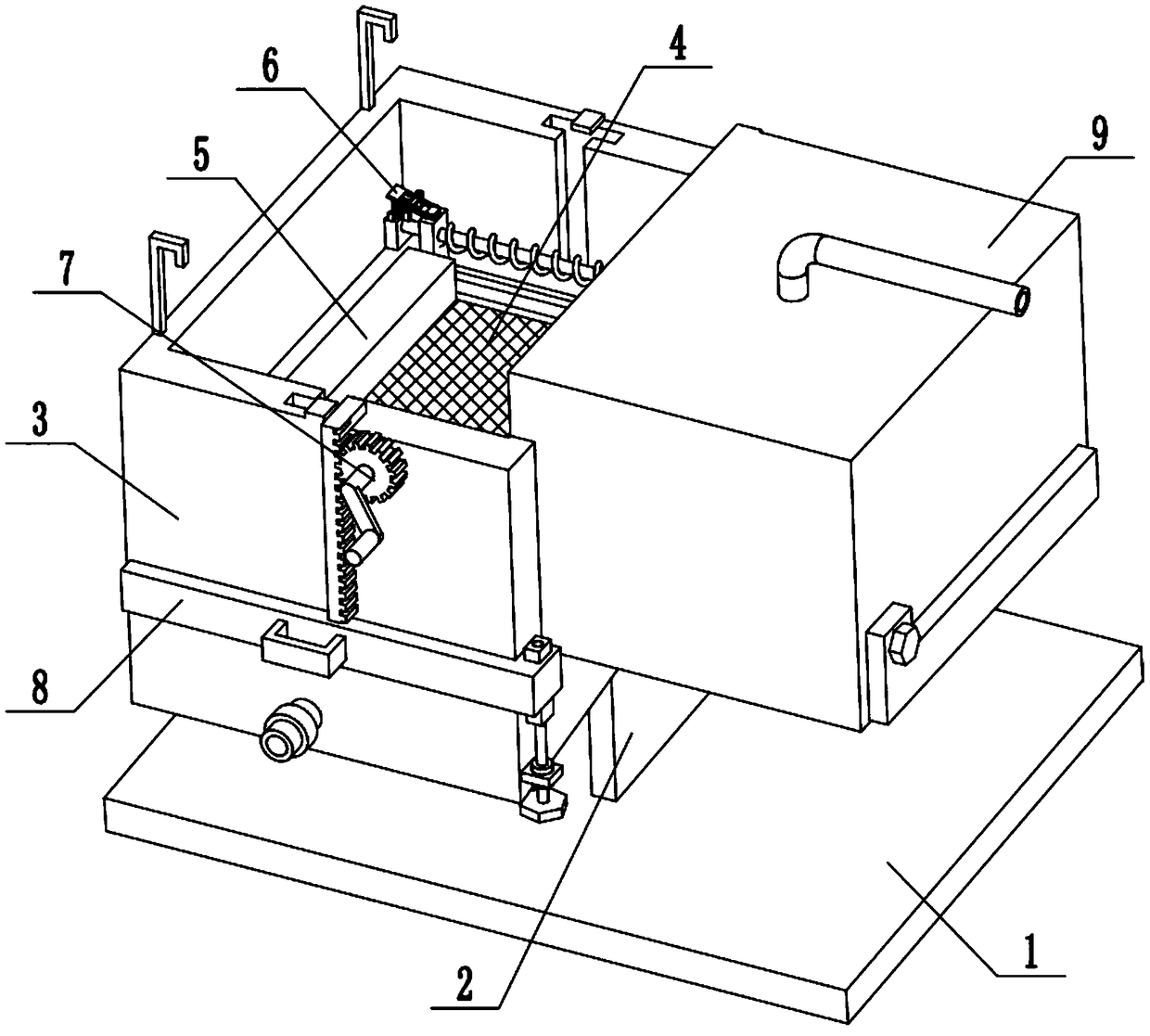
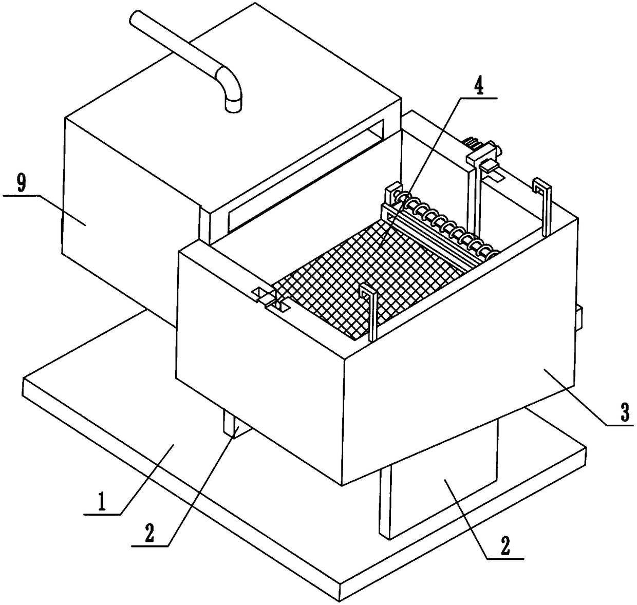
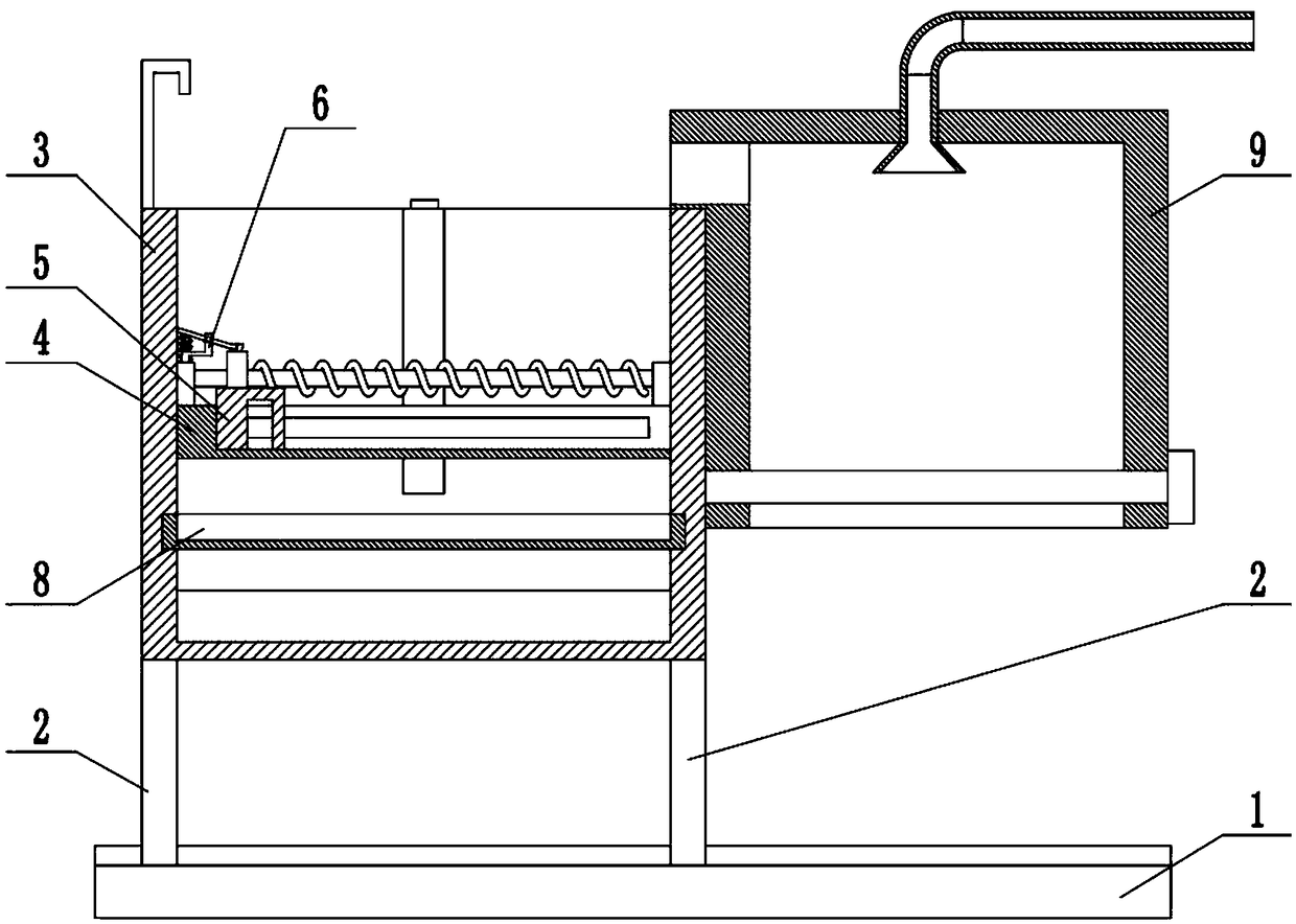
[0031] Combine below Figure 1-13Description of this embodiment, a coolant filter device for CNC machine tools, including a base 1, a support base 2, a coolant filter box 3, a primary filter assembly 4, a scraper 5, a clip 6, a control assembly 7, and a secondary filter assembly 8 and the chip cooling box 9, the coolant filter box 3 is fixedly connected to the base 1 through two support bases 2, the primary filter assembly 4 is slidably connected to the upper end of the coolant filter box 3, and the scraper 5 is slidably connected On the filter plate slide seat 4, two clips 6 are provided, and the two clips 6 are respectively fixedly connected to the front and rear ends of the left end of the primary filter assembly 4, and the two clips 6 are respectively clipped to the front and back of the scraper 5 At both ends, the control assembly 7 is rotatably connected to the upper end of the coolant filter box 3, the control assembly 7 is meshed with the primary filter assembly 4, and...

specific Embodiment approach 2

[0032] Combine below Figure 1-13 To illustrate this embodiment, the coolant filter box 3 includes a filter box body 3-1, a drain pipe 3-2 with a control valve, a front T-shaped chute 3-3, and a rear T-shaped chute 3-4 , block 3-5, filter plate chute 3-6, L-shaped rod 3-7 and top block 3-8; the filter box body 3-1 is fixedly connected to the base 1 through two support seats 2, and the filter box body The lower end of 3-1 slopes downward from the back to the front, the lower end of the front end of the filter box body 3-1 is fixedly connected and communicated with the drain pipe 3-2, the front T-shaped chute 3-3 and the rear T-shaped chute 3-4 They are respectively arranged symmetrically on the upper end of the front and rear end surfaces inside the filter box body 3-1. Two stoppers 3-5 are fixedly connected to the top surface of the filter box body 3-1. The two stoppers 3-5 are respectively located on the front T-shaped slide Above the groove 3-3 and the rear T-shaped chute 3...

specific Embodiment approach 3

[0033] Combine below Figure 1-13 To illustrate this embodiment, the primary filter assembly 4 includes a front T-shaped slider 4-1, a rear T-shaped slider 4-2, a vertical plate 4-3, a door-shaped frame 4-4, and a primary sieve plate 4-5, horizontal chute 4-6, vertical chute 4-7, rear spring seat plate 4-8, front spring seat plate 4-9, spring slide bar 4-10, compression spring I 4-11, L Type connecting plate 4-12 and tooth bar 4-13; Front T-shaped slide block 4-1 and rear T-shaped slide block 4-2 are slidably connected in front T-shaped chute 3-3 and rear T-shaped chute 3- 4, the front and rear ends of the door-shaped frame 4-4 are fixedly connected to the front T-shaped slider 4-1 and the rear T-shaped slider 4-2 through a vertical plate 4-3 respectively, and the primary sieve plate 4- 5. Fixedly connected in the door font frame 4-4, the front and rear end surfaces of the inside of the door font frame 4-4 are provided with horizontal chute 4-6, and the front and rear ends of...


PUM


Abstract

The invention relates to the technical field of machine tools, in particular to a numerically-controlled machine tool coolant filtering device which is characterized in that a coolant filtering box isfixedly connected onto a base through two supporting seats; a primary filtering assembly is slidably connected to the upper end of the coolant filtering box; a scraping plate is slidably connected onto a filtering plate sliding seat; two clamping parts are fixedly connected to the front and rear ends of the left end of the primary filtering assembly and connected to the front and rear ends of thescraping plate in a clamping manner; and a control assembly is rotationally connected to the upper end of the coolant filtering box. Through the primary filtering assembly and a secondary filtering assembly in the numerically-controlled machine tool coolant filtering device provided by the invention, a coolant can be subjected to double filtration; after being cooled, the coolant can be discharged for recycling, thereby improving the coolant recycling rate and bringing certain economic benefits; cuttings and solid particles in the coolant can be cooled, thereby protecting workers against accidental injuries caused by the high-temperature cuttings; and the secondary filtering assembly can be extracted so as to clear the cuttings and the solid particles.

Description

technical field [0001] The invention relates to the technical field of machine tools, in particular to a cooling fluid filtering device for a numerically controlled machine tool. Background technique [0002] A machine tool refers to a machine that manufactures a machine, also known as a machine tool or a tool machine, and is customarily referred to as a machine tool. Generally divided into metal cutting machine tools, forging machine tools and woodworking machine tools, etc. During the processing of iron parts, various machine tools used in machining workshops will generate a large amount of iron filings, which will remain in the machining coolant In the process of machine tool equipment, a large amount of dust, solid particle pollutants and other sundries will be mixed into the coolant during the working process. The coolant used in the operation of the existing machine tool is generally discharged directly to the outside, wasting resources, and After the coolant is recov...

Claims


Application Information

Patent Timeline
IPC IPC(8): B23Q11/10
CPCB23Q11/1069
Inventor 韩志荣
Owner 东莞市蓝拓数控机床有限公司
Why Eureka
Try Eureka