
Vacuum adsorption clamp

A vacuum adsorption and fixture technology, applied in the direction of manufacturing tools, workpiece clamping devices, etc., can solve the problems of uneven force on sheet workpieces, affecting the quality of sheet workpieces, and low adsorption force, so as to improve processing accuracy and service life , Uniform adsorption force, improve the effect of adsorption force

Pending Publication Date: 2019-03-19
CONPROFE TECH GRP CO LTD +1
View PDF8 Cites 2 Cited by
  • Summary
  • Abstract
  • Description
  • Claims
  • Application Information

AI Technical Summary

Problems solved by technology

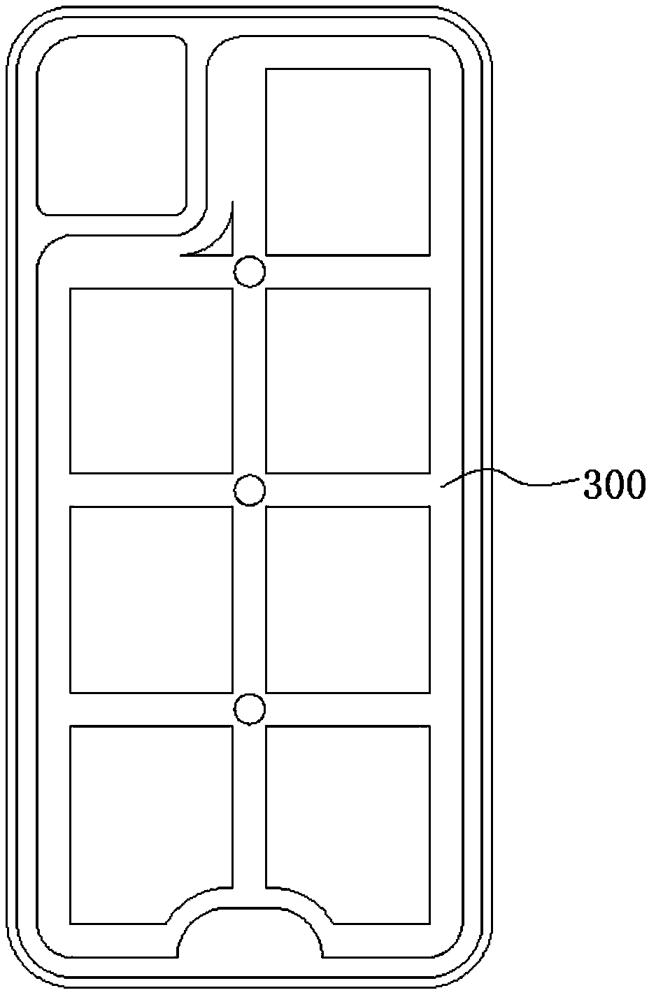
Similarly, when this kind of fixture is used, on the one hand, the side of the sheet-shaped workpiece in contact with the fixture is likely to produce serious Tian-shaped fixture marks, and on the other hand, the adsorption force received by the sheet-shaped workpiece is mainly concentrated on the position corresponding to the square-shaped groove 300 , the adsorption force around it is low, resulting in uneven force on the sheet-shaped workpiece, and craters and ring marks will appear on the other side of the sheet-shaped workpiece near the mounting hole of the forming camera, which seriously affects the quality of the sheet-shaped workpiece

Method used


Image

  • Vacuum adsorption clamp
  • Vacuum adsorption clamp
  • Vacuum adsorption clamp

Examples


Embodiment 1

[0046] See Figure 4 and Figure 5 As shown, the vacuum adsorption fixture of the present invention is schematically shown, which includes a fixed plate 10 and a workpiece adsorption block 20 above the fixed plate 10. The upper surface of the workpiece adsorption block 20 in this embodiment is used to absorb the workpiece to be processed. For example, sheet workpieces such as mobile phone screen glass or shell, the upper surface of the workpiece adsorption block 20 is provided with a number of first air holes 21 arranged in a ring structure near the outer edge of the workpiece, and is located in the ring structure surrounded by the first air holes 21. The inner side of the fixed plate 10 is provided with a number of second air holes 22 that run through the upper and lower surfaces of the workpiece adsorption block 20. The inside of the fixed plate 10 is provided with a sealed cavity 11 communicated with the second air holes 22, and the outer side of the fixed plate 10 is provi...

Embodiment 2

[0054] See Figure 8 and Figure 9 As shown, the difference between the workpiece adsorption block 20 in this embodiment and the first embodiment is that the lower surface of the workpiece adsorption block 20 is provided with a groove 26 that is opposite to and communicated with the sealed cavity 11, and the groove 26 The side wall is sealed and connected to the side wall of the sealed cavity 11, and the second air hole 22 penetrates from the upper surface of the workpiece adsorption block 20 to the groove 26, so as to reduce the overall weight of the workpiece adsorption block 20; one side of the fixed plate 10 is provided with a depression 13 , The air extraction hole 12 is located in the depression 13, so as to shorten the length of the air extraction hole 12, so as to improve the processing accuracy of the air extraction hole 12, improve the processing efficiency and reduce the processing cost.

[0055] Further, the workpiece adsorption block 20 is provided with an annula...

Embodiment 3

[0064] See Figure 10 , Figure 11 and Figure 12 As shown, the difference between the vacuum adsorption fixture in this embodiment and the second embodiment is that a plurality of sealed cavities 11 are arranged side by side inside the fixed plate 10, and a plurality of sealing cavities 11 are provided on the lower surface of the workpiece adsorption block 20. The groove 26 of position one-to-one correspondence (as Figure 12 shown in ), each groove 26 communicates with the sealed cavity 11 respectively, the side wall of the groove 26 is sealed and connected with the side wall of the sealed cavity 11 corresponding to it, and each groove 26 communicates with the second air hole 22 respectively; at the same time, The outside of fixed plate is provided with a plurality of air extraction holes 12 (as Figure 11 shown in ), each pumping hole 12 is connected to a vacuum pump, and each pumping hole 12 communicates with each sealed cavity 11 respectively.

[0065] In this embodim...


PUM


Abstract

The invention relates to a clamp, and specifically discloses a vacuum adsorption clamp. The vacuum adsorption clamp comprises a fixed plate and a workpiece adsorption block arranged on the fixed plate, wherein the upper surface of the workpiece adsorption block is used for adsorbing a sheet-shaped workpiece; a plurality of first air holes arranged in the form of an annular structure are formed ina position close to the edge of the outer side of the upper surface of the workpiece adsorption block, on the upper surface, the first air holes are blind holes, a plurality of second air holes penetrating through the upper surface and the lower surface of the workpiece adsorption block are formed in the inner side of the annular structure encircled by the plurality of first air holes, and each first air hole communicates with the adjacent second air hole through a ventilation groove; and a sealing cavity communicating with the second air holes is formed in the fixed plate, and air extractionholes communicating with the sealing cavity are formed in the outer side of the fixed plate. According to the vacuum adsorption clamp, the uniform overall adsorption force of the sheet-shaped workpiece can be achieved, the generation of volcanic vents, ring marks and jig marks is avoided, and the edge of the sheet-shaped workpiece can further be prevented from being tilted, so that the rigidity ofthe edge of the vacuum adsorption clamp is guaranteed.

Description

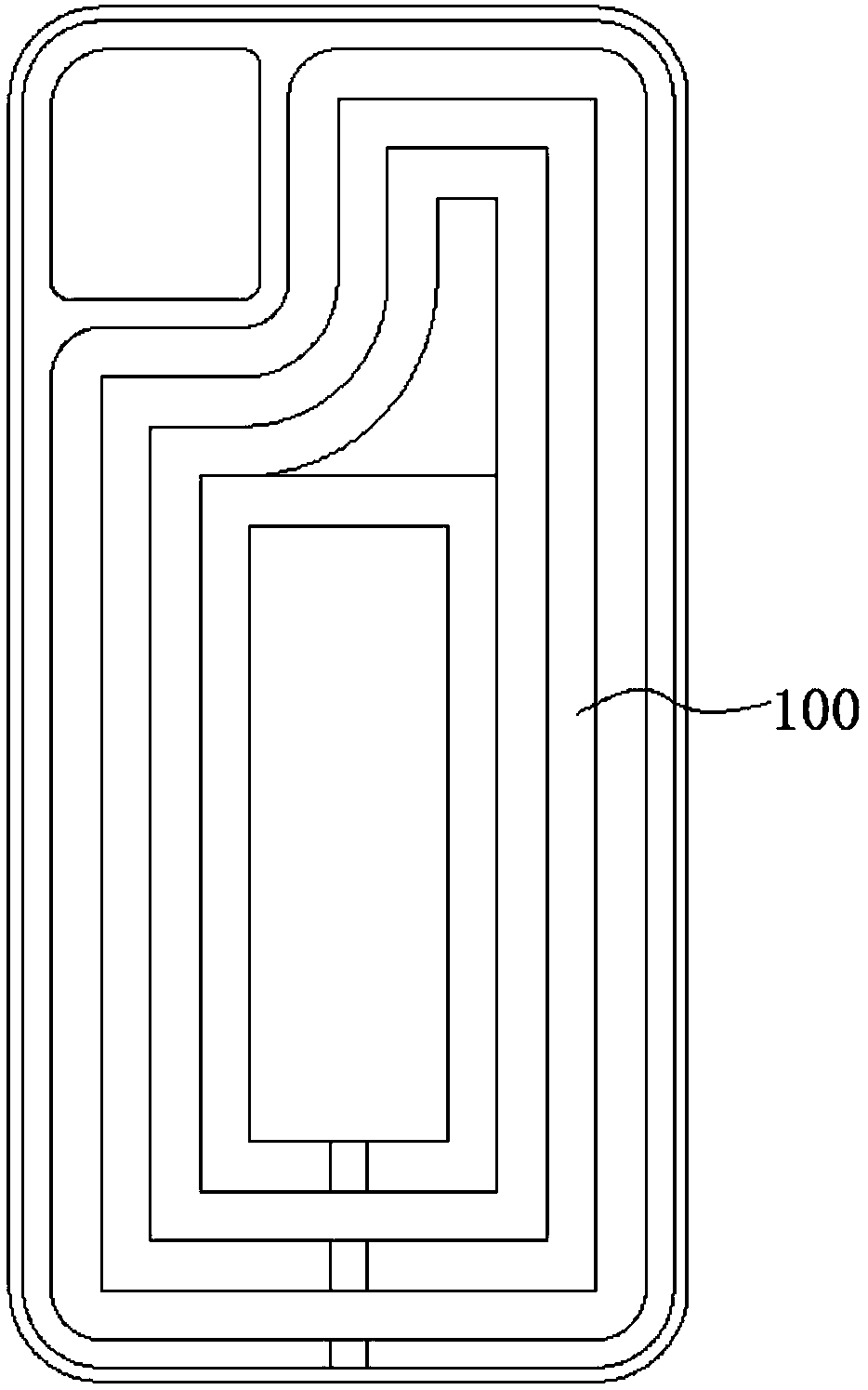
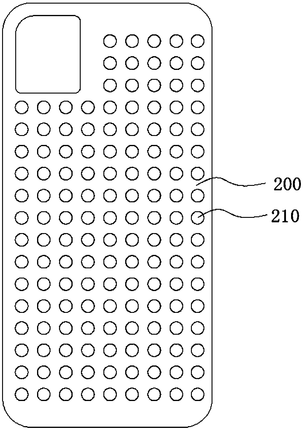
technical field [0001] The invention relates to a clamp, in particular to a vacuum adsorption clamp. Background technique [0002] The processing and manufacturing process of electronic equipment such as mobile phones and tablets requires extremely high precision. When processing thin sheet components such as screens or back covers of electronic equipment, it is necessary to fix the sheet workpiece to be processed first, and then process it. For fine processing, the selection of fixtures will have a great impact on the processing quality of sheet workpieces. In order to ensure the continuous fixation of the sheet-shaped workpiece during processing, and to adapt to the shape and material properties of the sheet-shaped workpiece, the industry usually uses vacuum adsorption fixtures to fix the sheet-shaped workpieces to be processed. At present, vacuum adsorption fixtures generally have the following Three types: [0003] The first, see figure 1 As shown, the top of the fixt...

Claims


Application Information

Patent Timeline
Patent Type & Authority Applications(China)
IPC IPC(8): B25B11/00
CPCB25B11/005
Inventor 李伟秋颜炳姜
Owner CONPROFE TECH GRP CO LTD
Learn More