Liquid ejecting head, liquid ejecting apparatus, and piezoelectric device

一种液体喷射头、液体的技术,应用在压电器件/电致伸缩器件、印刷等方向,能够解决粘着性恶化、易于发生迁移、配线短路或绝缘破坏等问题

Active Publication Date: 2019-03-19
SEIKO EPSON CORP
View PDF9 Cites 0 Cited by
  • Summary
  • Abstract
  • Description
  • Claims
  • Application Information

AI Technical Summary

Problems solved by technology

[0004] However, if a filler such as an underfill provided between the drive circuit and the channel-forming substrate is covered with a protective film to protect the channel-forming substrate from ink, there is a problem that the filler will generate If the gas is not exhausted to the outside, contamination will occur on the surface of the terminals of the drive circuit or the wiring connected to the terminals, and short-circuiting of the wiring or insulation breakdown will easily occur.
[0005] In addition, there is also a problem that, due to the gas generated from the filler, the adhesiveness of the joint surface between the drive circuit and the flow channel forming substrate is deteriorated, and migration tends to occur.

Method used


Image

  • Liquid ejecting head, liquid ejecting apparatus, and piezoelectric device
  • Liquid ejecting head, liquid ejecting apparatus, and piezoelectric device
  • Liquid ejecting head, liquid ejecting apparatus, and piezoelectric device

Examples


Embodiment approach 1

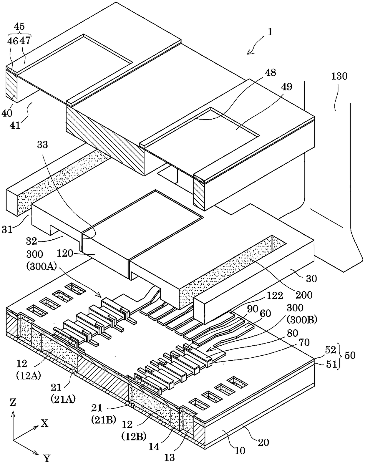
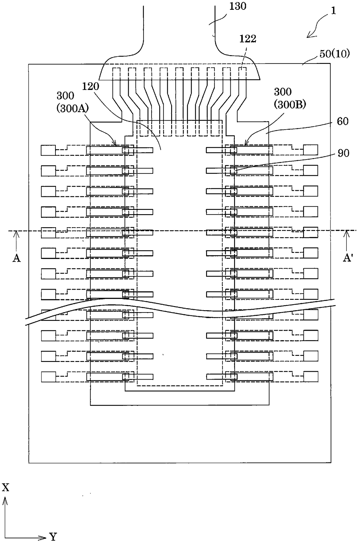
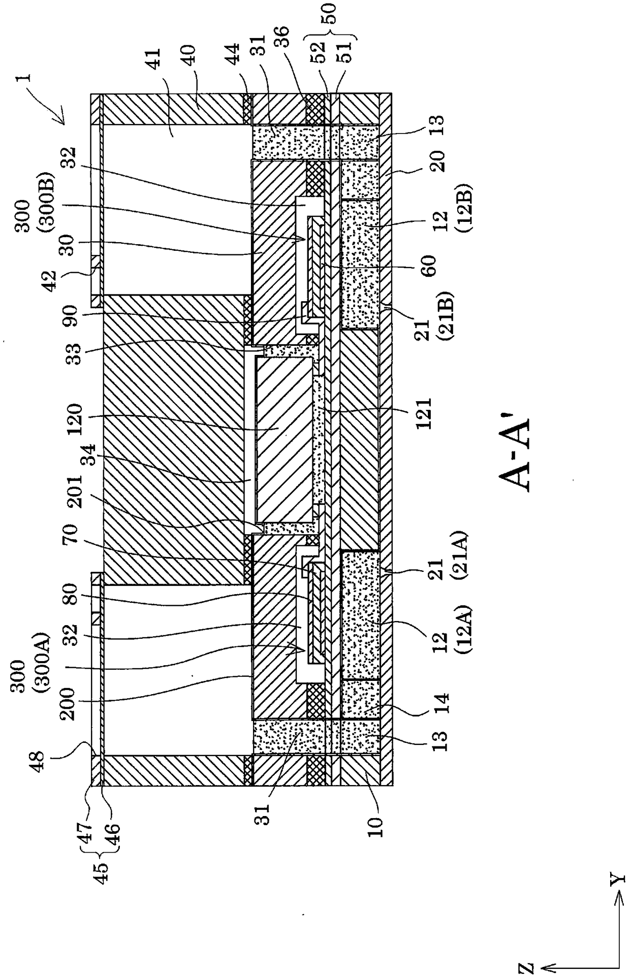
[0033] figure 1 It is an exploded perspective view of an inkjet recording head that is an example of the liquid ejection head according to Embodiment 1 of the present invention, figure 2 A plan view of a substrate forming a flow channel for an inkjet recording head, image 3 in accordance with figure 2 A cross-sectional view of the inkjet recording head on line A-A', Figure 4 for will image 3 An enlarged view of the main part.

[0034] As shown in the drawing, the channel forming substrate 10 constituting the ink jet recording head 1 (hereinafter, also simply referred to as the recording head 1) can be made of metal such as stainless steel or nickel (Ni), made of zirconia (ZrO X ) or alumina (Al X o Y ) represented by ceramic materials, glass ceramic materials and such as silicon oxide (SiO X ), magnesium oxide (MgO), lanthanum aluminate (LaAlO 3 ) Such oxides, etc. In this embodiment, the flow channel forming substrate 10 is formed of a single crystal silicon sub...

Embodiment approach 2

[0088] Figure 8 It is a cross-sectional view of an ink jet recording head as an example of a liquid ejecting head according to Embodiment 2 of the present invention. In addition, the same code|symbol is attached|subjected to the same member as the above-mentioned embodiment, and overlapping description is abbreviate|omitted.

[0089] Such as Figure 8 As shown, in the recording head 1 of this embodiment, the recessed portion 202 is formed on the protective film 200 provided on the bonding surface of the protective substrate 30 and the casing member 40 .

[0090] The concave portion 202 is not formed at the boundary portion of the bonding surface between the third liquid supply chamber 41 and the case member 40 , but is formed at a portion other than the boundary. In the present embodiment, a plurality of recesses 202 are arranged in parallel along the first direction X on the bonding surface between the protective substrate 30 and the case member 40 .

[0091] The concave ...

Embodiment approach 3

[0095] Figure 9 It is a cross-sectional view of an inkjet recording head that is an example of a liquid ejection head according to Embodiment 3 of the present invention. In addition, the same code|symbol is attached|subjected to the same member as the above-mentioned embodiment, and overlapping description is abbreviate|omitted.

[0096] Such as Figure 9 As shown, an atmosphere opening passage 43 is formed in the case member 40 as the flow channel member of the present embodiment, and the atmosphere opening passage 43 communicates the space 34 holding the drive circuit 120 with the outside. In the present embodiment, the atmosphere opening passage 43 is provided so as to penetrate the case member 40 in the third direction Z. As shown in FIG. That is, one end of the atmosphere opening passage 43 is opened to the space 34 , and the other end is opened to the side of the case member 40 opposite to the protective substrate 30 .

[0097] In addition, as in the first embodiment...


PUM


Abstract

The invention provides a liquid ejecting head, a liquid ejecting apparatus, and a piezoelectric device. The liquid ejecting head includes a flow path forming substrate (10); a protective substrate (30) that is bonded to the one surface side of the flow path forming substrate (10) and has a flow path (31); a flow path member (40) that is adhered to a side of the protective substrate (30) opposite to the flow path forming substrate (10); and a drive circuit (120) that is mounted in a space (34) formed so as to be surrounded by the flow path forming substrate (10), the protective substrate (30),and the flow path member (40); a filler (121) that is filled between the drive circuit (120) and the flow path forming substrate (10), and between the drive circuit (120) and the protective substrate(30); and a protective film (20) that is formed from an inner wall of the flow path of the protective substrate (30) to a boundary side with at least the inner wall of a bonding surface of the protective substrate (30) with the flow path member (40), in which the protective film (200) has an exposure hole (201) exposing at least a portion of a surface of the filler (121).

Description

technical field [0001] The present invention relates to a liquid ejection head for ejecting liquid, a liquid ejection device provided with the liquid ejection head, and a piezoelectric device having a piezoelectric element. Background technique [0002] As a piezoelectric device used for an inkjet type recording head, which is a representative example of a liquid ejection head, there is a piezoelectric device provided with an independent flow channel communicated with a nozzle, and an independent flow channel communicated with the independent flow channel. The flow path forming substrate of the liquid supply chamber; the piezoelectric element provided on one surface side of the flow path forming substrate via the vibrating plate. [0003] For an inkjet recording head having such a piezoelectric device, a technique has been proposed in which a drive circuit for driving a piezoelectric element is directly mounted on a flow channel forming substrate (for example, refer to Paten...

Claims


Application Information

Patent Timeline
Patent Type & Authority Applications(China)
IPC IPC(8): B41J2/14B41J2/01H01L41/09
CPCB41J2/01B41J2/14201H10N30/20B41J2/1606B41J2/161B41J2/1623B41J2/1628B41J2/1642B41J2/1646B41J2002/14419B41J2002/14491B41J2/14233B41J2002/14306
Inventor 中山雅夫福田俊也平井荣树矢崎士郎中尾元
Owner SEIKO EPSON CORP
Why Eureka
Try Eureka