Magnetism measuring device, manufacturing method of magnetism measuring device, and manufacturing method of gas cell

A technology of metering device and manufacturing method, applied in magnetic resonance measurement, single-equipment manufacturing, fixed-capacity gas storage tank, etc., can solve problems such as insufficient processing, damage to the airtightness of ampoules, and low evaporation of alkali metals

Inactive Publication Date: 2016-05-25
SEIKO EPSON CORP
View PDF6 Cites 6 Cited by
  • Summary
  • Abstract
  • Description
  • Claims
  • Application Information

AI Technical Summary

Problems solved by technology

[0004] In addition, in the process of forming the through-hole, in the process of forming only one through-hole by irradiating laser light at one position, there may be cases where the airtightness of the ampoule cannot be broken due to insufficient processing in the depth direction. case, or even if a through hole can be formed, the amount of evaporation of the alkali metal in the ampoule is small, and it takes a long time until the alkali metal gas fills the main chamber
However, when the process of irradiating laser light at one position is repeated many times in order to reliably form the through-hole and fill the main chamber with alkali metal gas in a short time, there is a problem of increasing the number of manufacturing processes.

Method used


Image

  • Magnetism measuring device, manufacturing method of magnetism measuring device, and manufacturing method of gas cell
  • Magnetism measuring device, manufacturing method of magnetism measuring device, and manufacturing method of gas cell
  • Magnetism measuring device, manufacturing method of magnetism measuring device, and manufacturing method of gas cell

Examples


no. 1 approach

[0105]

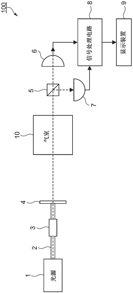
[0106] refer to figure 1 The configuration of the magnetic measuring device according to the first embodiment will be described. figure 1 It is a block diagram showing the structure of the magnetism measuring device of this embodiment. The magnetism measuring device 100 of the present embodiment is a magnetism measuring device using a nonlinear magneto-optical rotation (Nonlinear Magneto-Optical Rotation: NMOR). The magnetic measurement device 100 is used as a living body state measuring device (magnetocardiometer, magnetoencephalometer, etc.) . The magnetic measuring device 100 can also be used in a metal detector or the like.

[0107] Such as figure 1 As shown, the magnetic measuring device 100 includes a light source 1, an optical fiber 2, a connector 3, a polarizing plate 4, a gas chamber 10, a polarized light separator 5, a photodetector (PhotoDetector: PD) 6, a photodetector 7, and a signal processing circuit. 8 and a display device 9 . Alkali metal gas ...

no. 2 approach

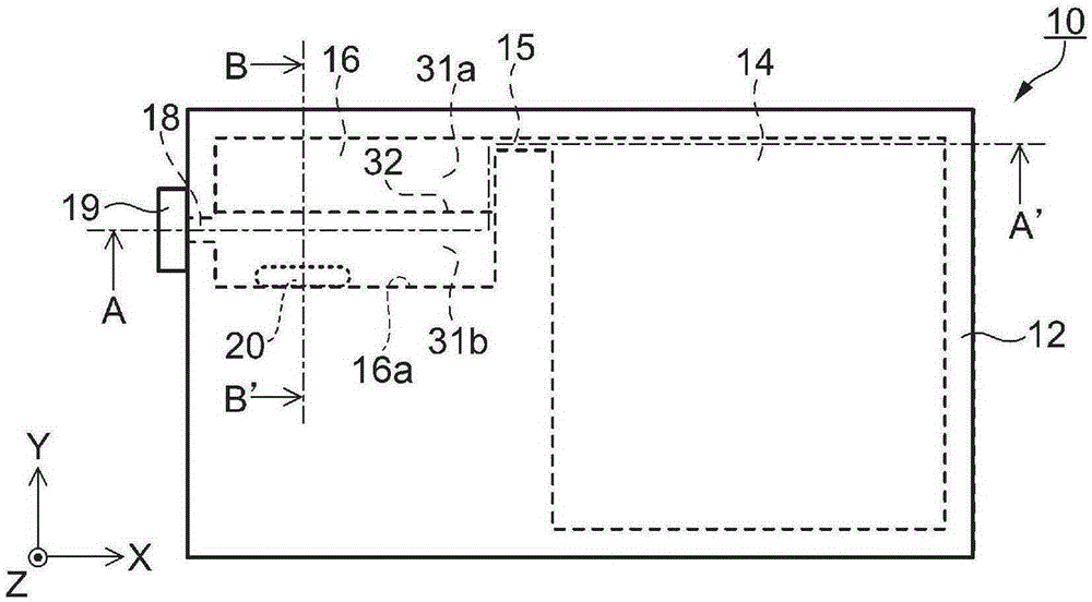
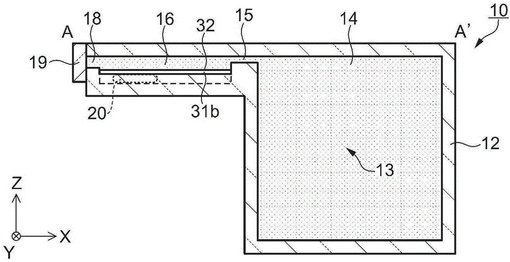
[0160] In the second embodiment, the cross-sectional shape of the storage portion 16 is different from that of the first embodiment in that a concave portion having a valley-shaped cross-section is formed by two inclined surfaces 31a and 31b. refer to Figure 7A , Figure 7B , Figure 7C , Figure 8A as well as Figure 8B Differences between the structure and cross-sectional shape of the gas cell of the second embodiment and the arrangement of ampoules from the first embodiment will be described. In addition, the same code|symbol is attached|subjected to the structural element common to 1st Embodiment, and the description is abbreviate|omitted.

[0161] Figure 7A as well as Figure 7B It is a schematic diagram showing the structure of the gas cell of the second embodiment. Explain in detail, Figure 7A is a schematic top view of the gas chamber, Figure 7B is along Figure 7A A schematic sectional view of the A-A' line, Figure 7C is a partial side view of the gas ...

no. 3 approach

[0174] In the third embodiment, the direction of inclination of the two inclined surfaces of the storage portion is different from the direction of the longitudinal direction of the placed ampoules compared to the first embodiment. refer to Figure 9A , Figure 9B , Figure 9C as well as Figure 9D Differences between the structure and cross-sectional shape of the gas cell of the third embodiment and the arrangement of ampoules from the first embodiment will be described. In addition, the same code|symbol is attached|subjected to the structural element common to 1st Embodiment, and the description is abbreviate|omitted.

[0175] Figure 9A , Figure 9B , Figure 9C as well as Figure 9D It is a schematic diagram showing the structure of the gas cell of the third embodiment. Explain in detail, Figure 9A is a schematic top view of the gas chamber, Figure 9B is along Figure 9A A schematic sectional view of the D-D' line, Figure 9C as well as Figure 9D It is a sc...


PUM


Abstract

The invention provides a magnetism measuring device which can stably and preciously performing metering, a manufacturing method of the magnetism measuring device, and a manufacturing method of a gas cell. The magnetism measuring device (100) includes: a gas cell (10) which includes a cell portion (12) that has a main chamber (14), a reservoir (16), a communication hole (15) which allows the main chamber and the reservoir to communicate with each other, and an opening (18) provided in the reservoir, a sealing portion (19) which seals the opening, an ampoule (20) disposed in the reservoir, and an alkali metal gas (13) which fills the main chamber and the reservoir (16). The ampoule is disposed at a predetermined position in the reservoir, and the opening is provided at a position that is distant from the predetermined position.

Description

technical field [0001] The present invention relates to a magnetic metering device, a gas chamber, a method for manufacturing the magnetic metering device, and a method for manufacturing the gas chamber. Background technique [0002] There is known an optical pump type magnetometer that measures a magnetic field from a rotation angle of a plane of polarization by irradiating linearly polarized light to a gas cell sealed with an alkali metal gas. Patent Document 1 discloses a magnetic measuring device that includes a gas chamber that accommodates an ampoule in which an alkali metal is sealed in a storage portion (ampule storage chamber), and that the ampoule is irradiated with laser light to generate The glass tube of the ampoule has a through hole, and the alkali metal in the ampoule is evaporated, and the vapor (gas) is filled into the main chamber from the storage part through the communication hole. [0003] However, when the ampoule is irradiated with laser light, if th...

Claims


Application Information

Patent Timeline
Patent Type & Authority Applications(China)
IPC IPC(8): G01R33/02
CPCG01R33/26F17C3/00G01R33/02G01R33/0052
Inventor 藤井永一
Owner SEIKO EPSON CORP
Why Eureka
Try Eureka