
Hardware system of printer

A hardware system and printer technology, applied in printing devices, printing, etc., can solve the problems of inability to fade, withstand the test of time, and long-term preservation of text, and achieve good printing results.

Pending Publication Date: 2019-03-19
深圳市美松智能设备有限公司
View PDF0 Cites 2 Cited by
  • Summary
  • Abstract
  • Description
  • Claims
  • Application Information

AI Technical Summary

Problems solved by technology

[0003] Because there are many labels, it must be able to withstand the test of time, remain unchanged for a long time, the text must be preserved for a long time, cannot fade, cannot be worn due to contact with solvents, cannot be deformed and discolored due to high temperature, etc., so it is necessary to use a special The printing media and printing materials of different materials can guarantee these characteristics, which cannot be achieved by general inkjet printing technology, nor can laser printing, and the effect of needle punching and the original design can not meet the requirements, so there is the emergence of thermal transfer printing technology.
[0004] At present, the existing thermal transfer printers on the market have an effective printing width of less than 300mm, which cannot meet the requirements of some special places, such as the logo on the high-voltage transformer box, etc., and the multi-thermal sheet splicing printing system based on MCU control can perfectly solve the corresponding problems above

Method used


Image

  • Hardware system of printer
  • Hardware system of printer
  • Hardware system of printer

Examples


Embodiment

[0042] Explanation of terms:

[0043] MCU: Micro Controller Unit (micro control unit), also known as single-chip microcomputer (Single Chip Microcomputer) or single-chip microcomputer.

[0044] SDRAM: Synchronous Dynamic Random Access Memory (Synchronous Dynamic Random Access Memory)

[0045] LCD: Liquid Crystal Display (liquid crystal display)

[0046] LCD display parameters: CLOCK: pixel clock;

[0047] VS: Vertical Sync (horizontal synchronization)

[0048] HS: Horizontal Sync (vertical synchronization)

[0049] DE: Data Enable (data valid enable)

[0050] DATA: display data

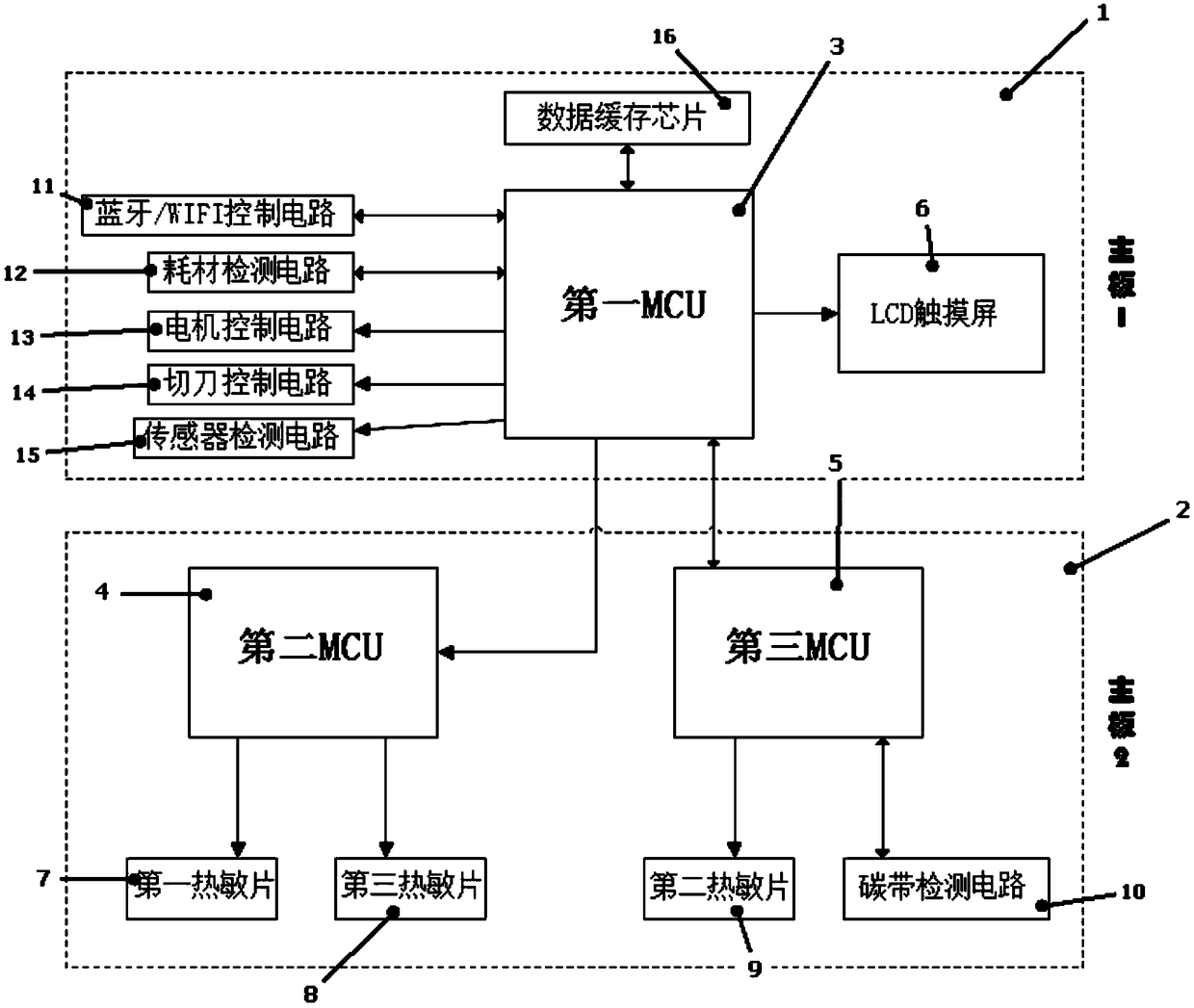
[0051] Such as figure 1 As shown, the present invention provides a hardware system of a printer, including a first MCU 3, a second MCU 4, a third MCU 5, a data cache chip 16, a wireless control circuit 11, a consumable detection circuit 12, a motor control circuit 13, a cutting Knife control circuit 14, sensor detection circuit 15, touch screen 6, first thermal sheet 7, second thermal sheet 9, ...


PUM


Abstract

The invention discloses a hardware system of a printer. The hardware system of the printer comprises a first MCU, a second MCU, a third MCU, a data cache chip, a wireless control circuit, a consumabledetection circuit, a motor control circuit, a cutter control circuit, a sensor detection circuit, a touch screen, a first thermosensitive chip, a second thermosensitive chip, a third thermosensitivechip and a thermal transfer ribbon detection circuit; the first MCU is electrically connected with the second MCU, the third MCU, the data cache chip, the wireless control circuit, the consumable detection circuit, the motor control circuit, the cutter control circuit, the sensor detection circuit and the touch screen; the second MCU is electrically connected with the first thermosensitive chip and the third thermosensitive chip; and the third MCU is electrically connected with the second thermosensitive chip and the thermal transfer ribbon detection circuit. According to the printer, large-format printing can be achieved, a printed nameplate can be kept for a long term, and the printing effect is good.

Description

technical field [0001] The invention relates to the technical field of printers, in particular to a hardware system of a printer. Background technique [0002] Thermal transfer printing technology has been used in the production of fabric thermal transfer printing for a long time. With the rapid development of high technology, thermal transfer printing technology has become more and more widely used. There are heat press transfer type and sublimation transfer type from the classification of ink varieties. From the classification of the transferred materials, there are fabrics, plastics (plates, sheets, films), ceramics and metal coated plates, etc.; from the classification of printing methods, it can be divided into screen printing, flat printing, gravure printing, embossing, inkjet and ribbon Printing, etc.; from the classification of substrates, there are thermal transfer paper and thermal transfer plastic film. [0003] Because there are many labels, it must be able to ...

Claims


Application Information

Patent Timeline
IPC IPC(8): B41J2/32B41J29/393
CPCB41J2/32B41J29/393
Inventor 黄尤川
Owner 深圳市美松智能设备有限公司
Learn More