Supercharge Your Innovation With Domain-Expert AI Agents!

A built-in multi-layer frustum-shaped tube superimposed phase-separation overflow device

A technology of overflow device and multi-layer circle, which is applied in the direction of measurement, wellbore/well components, earthwork drilling and production, etc., to achieve the effect of reducing influence, improving measurement accuracy, and improving measurement accuracy

Active Publication Date: 2022-03-22
PETROCHINA CO LTD +1
View PDF10 Cites 0 Cited by
  • Summary
  • Abstract
  • Description
  • Claims
  • Application Information

AI Technical Summary

Problems solved by technology

[0002] In the process of oil well production, mastering the flow and water content of each production layer of the oil well has important guiding significance for the design of geological schemes and the adjustment of measures. Traditionally, turbine flowmeters are usually used to measure the flow of oil wells, but there is a problem of sand sticking , so for many years have been continuously developing flowmeters that can be used to measure oil / water two-phase flow or oil / gas / water multiphase flow without moving parts. In recent years, Daqing Oilfield Testing Company has developed electromagnetic flowmeters Combining the characteristics of the components with the ability to measure flow in weakly conductive fluids, an electromagnetic flowmeter that can be used in high water-cut wells has been designed. Over the past three years, more than 30 wells have obtained qualified data. Through the application, it is found that the field needs to be further expanded. Adaptive range of water content of flowmeter and lower flow limit

Method used


Image

  • A built-in multi-layer frustum-shaped tube superimposed phase-separation overflow device
  • A built-in multi-layer frustum-shaped tube superimposed phase-separation overflow device
  • A built-in multi-layer frustum-shaped tube superimposed phase-separation overflow device

Examples


Embodiment Construction

[0019] The following will clearly and completely describe the technical solutions in the embodiments of the present invention with reference to the accompanying drawings in the embodiments of the present invention. Obviously, the described embodiments are only some, not all, embodiments of the present invention. Based on the embodiments of the present invention, all other embodiments obtained by persons of ordinary skill in the art without making creative efforts belong to the protection scope of the present invention.

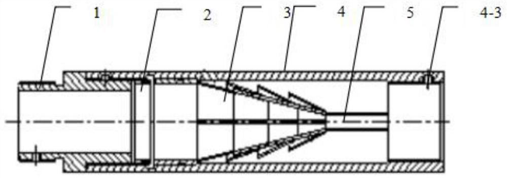
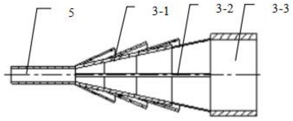
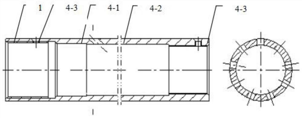
[0020] see Figure 1-7 , the present invention provides a technical solution: multi-layer frustum-shaped tube superimposed overflow device structure such as image 3 As shown, it includes 1 transition short connection 2 compression ring 3 multi-stage conical fluid channel 4, outer cylinder 5, wire-passing pipe. Figure 4 It is a schematic diagram of the main channel structure formed by superimposing multi-layer frustum-shaped tubes, including 3-1, multi-stage...


PUM


Abstract

The invention discloses a built-in multi-layer frustum-shaped tube superimposed phase-separation overflow device. The advantage of this technology is that the superimposed design of multi-layer frustum-shaped tubes can effectively separate the light phase in the downhole fluid and pass it through. The liquid outlet discharges the instrument, which reduces the influence of light weight on the measurement results of the instrument and improves the measurement accuracy of the instrument. Connect the device with the electromagnetic flowmeter and place it on the upper end of the current collector. When measuring the flow rate, the downhole fluid first passes through the device, and then passes through the electromagnetic flow sensor. Due to gravity, when the fluid flows through the proportional overflow device, it will affect the instrument measurement. Part of the resulting light phase can be discharged from the small hole on the device to improve the measurement accuracy of the electromagnetic flowmeter. The electromagnetic flowmeter is combined with an equiproportional circular overflow device and calibrated in a laboratory simulation well. As shown in Figure 1, the oil-water two-phase flow is selected for calibration, and the flow range is 2m 3 / d‑55 m 3 / d, 10m 3 / d a measurement point 5m 3 / d Encrypted measurement, the water content selection range is 40%‑100%.

Description

technical field [0001] The invention relates to the technical field of a built-in multi-layer frustum-shaped tube superimposed phase-separation overflow device, in particular to a built-in multi-layer frustum-shaped tube superimposed phase-separated overflow device. Background technique [0002] In the process of oil well production, mastering the flow and water content of each production layer of the oil well has important guiding significance for the design of geological schemes and the adjustment of measures. Traditionally, turbine flowmeters are usually used to measure the flow of oil wells, but there is a problem of sand sticking , so for many years have been continuously developing flowmeters that can be used to measure oil / water two-phase flow or oil / gas / water multiphase flow without moving parts. In recent years, Daqing Oilfield Testing Company has developed electromagnetic flowmeters Combining the characteristics of the components with the ability to measure flow in...

Claims


Application Information

Patent Timeline
Patent Type & Authority Patents(China)
IPC IPC(8): E21B47/00
CPCE21B47/00
Inventor 胡金海张玉辉刘艳玲刘兴斌王延军刘晓磊李屹威黄春辉杜佳楠罗来军
Owner PETROCHINA CO LTD
Features
  • R&D
  • Intellectual Property
  • Life Sciences
  • Materials
  • Tech Scout
  • Unparalleled Data Quality
  • Higher Quality Content
  • 60% Fewer Hallucinations
Learn More