
Connecting-rod-free hot air engine transmission mechanism and connecting-rod-free hot air engine transmission system

A transmission mechanism and transmission system technology, which is applied to machines/engines, combustion engines, engine components, etc., can solve problems such as energy loss, insufficient vibration and noise reduction effect, and reduced heat engine efficiency, and reduce vibration noise, weight, etc. Light weight, improved efficiency and reliability

Active Publication Date: 2019-03-19
SHANGHAI MICROPOWERS
View PDF10 Cites 2 Cited by
  • Summary
  • Abstract
  • Description
  • Claims
  • Application Information

AI Technical Summary

Problems solved by technology

At the same time, the side thrust of the piston acts on the inner surface of the cylinder liner to cause friction and cause energy loss, resulting in a decrease in the efficiency of the heat engine
In the design of the crank-link mechanism, the appropriate balance structure can be calculated through dynamic balance to reduce the vibration of the engine. However, due to technical limitations in design, manufacturing, and assembly, the effect of reducing vibration and noise is not obvious enough.

Method used


Image

  • Connecting-rod-free hot air engine transmission mechanism and connecting-rod-free hot air engine transmission system
  • Connecting-rod-free hot air engine transmission mechanism and connecting-rod-free hot air engine transmission system
  • Connecting-rod-free hot air engine transmission mechanism and connecting-rod-free hot air engine transmission system

Examples


Embodiment Construction

[0051] In order to more clearly illustrate the embodiments of the present invention or the technical solutions in the prior art, the specific implementation manners of the present invention will be described below with reference to the accompanying drawings. Obviously, the accompanying drawings in the following description are only some embodiments of the present invention, and those skilled in the art can obtain other accompanying drawings based on these drawings and obtain other implementations.

[0052] In order to make the drawing concise, the parts related to the present invention are only schematically shown in each drawing, and they do not represent the actual structure of the product. In addition, to make the drawings concise and easy to understand, in some drawings, only one of the components having the same structure or function is schematically shown, or only one of them is marked. Herein, "a" not only means "only one", but also means "more than one". In this arti...


PUM


Abstract

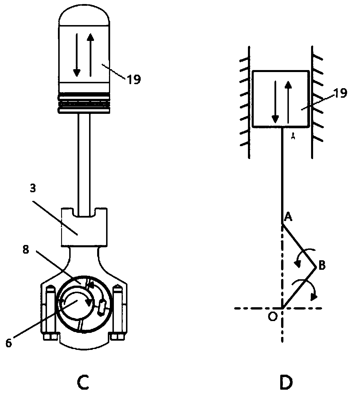
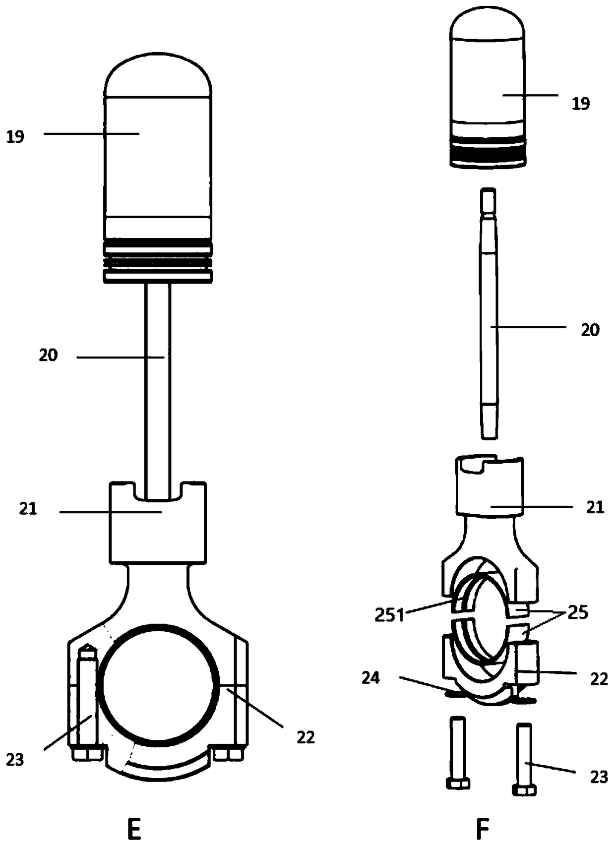
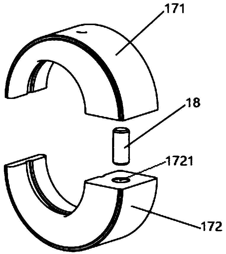
The invention discloses a connecting-rod-free hot air engine transmission mechanism and a connecting-rod-free hot air engine transmission system. The connecting-rod-free hot air engine transmission mechanism comprises a piston assembly and an eccentric wheel sliding block. The eccentric wheel sliding block comprises a first moon-shaped sliding block and a second moon-shaped sliding block oppositeto the first moon-shaped sliding block. A shaft neck hole for sleeving a crankshaft is formed by the inner side walls of the first moon-shaped sliding block and the second moon-shaped sliding block. The outer side wall of the eccentric wheel sliding block is formed by the outer side walls of the first moon-shaped sliding block and the second moon-shaped sliding block. The distance between the circle centers of the shaft neck hole and the eccentric wheel sliding block is equal to the crank throw eccentric distance of the crankshaft. The piston assembly is connected with the eccentric wheel sliding block, the rotating direction of the eccentric wheel sliding block is opposite to that of the crankshaft, and the rotating speed of the eccentric wheel sliding block is equal to that of the crankshaft. Under certain displacement of a hot air engine, the turning radius of a crank is reduced to be half of the turning radius of a crank connecting rod structure, the rotating inertia force of the crank is small, the side thrust of a piston, crankshaft stress and bearing loads are reduced, energy losses are reduced, the service life of parts of the hot air engine is prolonged, and the efficiencyand the reliability of the hot air engine are improved.

Description

technical field [0001] The invention relates to the technical field of a heat engine, in particular to a transmission mechanism of a heat engine without a connecting rod and a transmission system of a heat engine without a connecting rod. Background technique [0002] The heat engine is a closed-cycle piston engine with external heating, which is mainly composed of an external heating system, a working cycle system, a transmission system, an auxiliary system, and a monitoring system. [0003] The transmission system is the main component of the output power of the heat engine, which is responsible for converting the reciprocating linear motion of the piston into the rotary motion of the output shaft. At present, most of the four-cylinder heat engines and eight-cylinder heat engines adopt crank-link mechanism, and the transmission forms of the mechanism include double-crank U-type and single-crank V-type. The double-crank U-shaped transmission structure is mainly composed of...

Claims


Application Information

Patent Timeline
IPC IPC(8): F01B31/04F01B31/00F01B9/02
CPCF01B9/02F01B31/00F01B31/04Y02T10/12
Inventor 刘永杰朱辰元周建明朱天宇程艳萍
Owner SHANGHAI MICROPOWERS
Learn More