
FPGA implementation method suitable for pulse compression of large pulse width signal

A technology of pulse compression and implementation method, which is applied in the direction of radio wave measurement systems and instruments, can solve the problems of slow speed, inflexible control mode, poor anti-interference ability, etc., to reduce the demand for hardware resources, eliminate hidden dangers of signal truncation, The effect of ensuring integrity

Pending Publication Date: 2019-03-19
重庆秦嵩科技有限公司
View PDF3 Cites 1 Cited by
  • Summary
  • Abstract
  • Description
  • Claims
  • Application Information

AI Technical Summary

Problems solved by technology

The hardware implementation of pulse compression technology has probably gone through several stages, from analog pulse compression to digital pulse compression with DSP devices as the core, and then to digital pulse compression with field programmable gate array FPGA devices as the core. The analog pulse compression factor It has the disadvantages of poor anti-interference ability and inflexible control mode, but it has been replaced by digital pulse compression. The pulse compression scheme with DSP devices as the core has also been gradually adopted due to the shortcomings of low efficiency, slow speed, and large delay in implementing digital signal algorithms. It is replaced by the pulse compression scheme with FPGA as the core. FPGA is a digital integrated circuit device that can be programmed by users to realize the required logic functions. , the emergence of FPGA is only to replace traditional digital logic circuits, but as it is easy to achieve parallel computing and other excellent performance, it has gradually become a development trend to use FPGA to implement various signal processing algorithms

Method used


Image

  • FPGA implementation method suitable for pulse compression of large pulse width signal
  • FPGA implementation method suitable for pulse compression of large pulse width signal
  • FPGA implementation method suitable for pulse compression of large pulse width signal

Examples


Embodiment 1

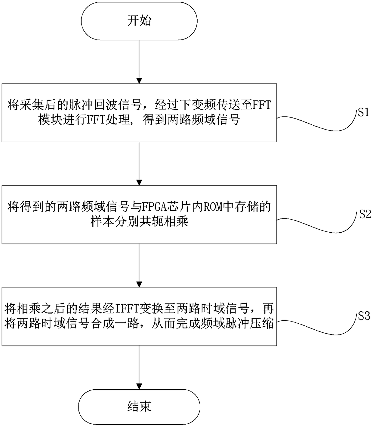
[0051] Such as figure 1 As shown, the present invention provides a kind of FPGA implementation method that is applicable to the pulse compression of large pulse width signal, and its implementation method is the following steps:

[0052] (S1) The collected pulse echo signal is sent to the FFT module for FFT processing through down-conversion to obtain two frequency domain signals;

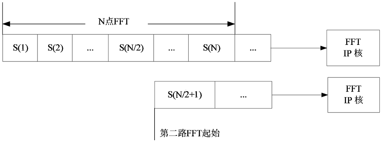
[0053] In (S1), such as image 3 As shown, FFT processing is performed on the pulse echo signal, including the following steps:

[0054] (a1) Obtaining a time-domain baseband signal by down-converting the collected pulse echo signal;

[0055] (a2) transforming the obtained time-domain baseband signal into the frequency domain, thereby obtaining two channels of frequency-domain signals;

[0056] In (a2), the obtained time-domain baseband signal is converted to the frequency domain, which is specifically by calling the FFT module integrated in the FPGA chip to perform N-point fast Fourier transform...

Embodiment 2

[0079] For further explanation, a simple example is given below.

[0080] A portable radar with a working bandwidth of 40MHz and a pulse width of 20us, mainly detects small cars, motorcycles, bicycles and pedestrians.

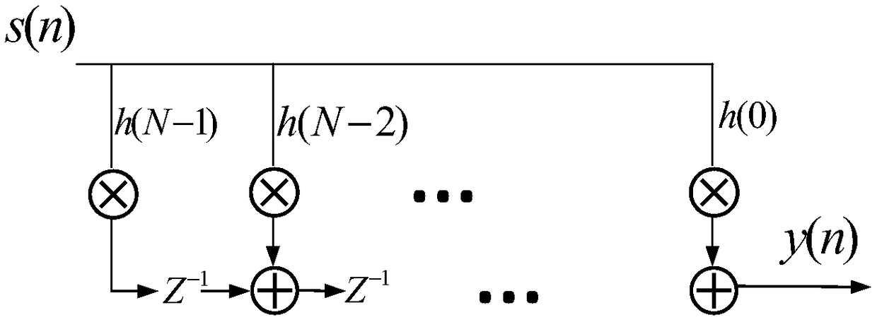
[0081] According to the working bandwidth of the radar, set the baseband sampling rate to 50MHz, then the number of pulse compression samples is 1000 points, and the time domain pulse compression imports the samples into the filter. Frequency-domain pulse compression needs to do FFT transformation on the sample, and then store the result in FPGA on-chip ROM, and the number of FFT points is 2048 points.

[0082] The intermediate frequency of the system is 140MHz, and the bandpass sampling rate is 200MHz. After the AD signal is collected, it is down-converted and extracted, and the sampling rate is reduced to 50MHz, and the clock rate is 200MHz. For time-domain pulse compression, a faster clock rate can be used in exchange for resources.

[0083] The FPGA chip o...


PUM


Abstract

The invention provides an FPGA implementation method suitable for pulse compression of a large pulse width signal. The method comprises the following steps of (S1) transmitting a pulse echo signal collected after the down-conversion to a FFT module for FFT processing to obtain a two-channel frequency domain signal; (S2) conjugating and multiplying the obtained two-channel frequency domain signal by samples stored in the ROM in an FPGA chip; (S3) converting the multiplied result to a two-channel time domain signal by IFFT, and combining the two-channel time domain signal into one channel to complete the frequency domain pulse compression. The method reduces the problem of the requirement of hardware resources when the large pulse width signal is compressed, and achieves the pulse compression function of the large pulse width signal in the FPGA. The method has strong flexibility and has a strong practical value and a promotion value.

Description

technical field [0001] The invention relates to the technical field of radar signal processing, in particular to an FPGA implementation method suitable for pulse compression of large pulse width signals. Background technique [0002] Since the late 1950s, with the rapid development of flight technology, aircraft, missiles, satellites and other flight equipment have adopted radar as one of the methods of control and detection. In terms of performance, more and more strict requirements are put forward. According to the theory of radar signal processing, in ordinary pulse radar, there is an irreconcilable contradiction between the operating range and the range resolution. [0003] Pulse compression has become an important technology because it can solve the contradiction between target detection range and distance-resolution. Pulse compression technology is a good practical application of matched filtering theory and correlation receiving theory. Its proposal is very A good so...

Claims


Application Information

Patent Timeline
Patent Type & Authority Applications(China)
IPC IPC(8): G01S7/295
CPCG01S7/295
Inventor 周灿荣凌清平
Owner 重庆秦嵩科技有限公司
Learn More