A scintillator array luminescence decay time testing method

A technology of luminescence attenuation and test method, which is applied in the field of radiation detectors, can solve the problems of indistinguishable scintillator performance and low scintillator efficiency, and achieve the effect of improving test efficiency

Active Publication Date: 2020-04-28
JIANGSU SINOGRAM MEDICAL TECH CO LTD
View PDF5 Cites 0 Cited by
  • Summary
  • Abstract
  • Description
  • Claims
  • Application Information

AI Technical Summary

Problems solved by technology

In this application, it is obviously too inefficient to use the traditional scintillator performance test method to test each scintillator during the scintillator array manufacturing process, and the traditional single scintillator performance test method cannot be used in the final detection of the array performance. Distinguish the performance of each scintillator, so there is a need for a more efficient and accurate method to solve this problem

Method used


Image

  • A scintillator array luminescence decay time testing method
  • A scintillator array luminescence decay time testing method
  • A scintillator array luminescence decay time testing method

Examples


Embodiment 1

[0039] This embodiment provides a method for testing the luminescence decay time of a scintillator array, the method comprising the following steps:

[0040] Step S1: The scintillation light emitted by the scintillator array under test is received by a correspondingly set photodetection array, and converted into an electrical pulse signal.

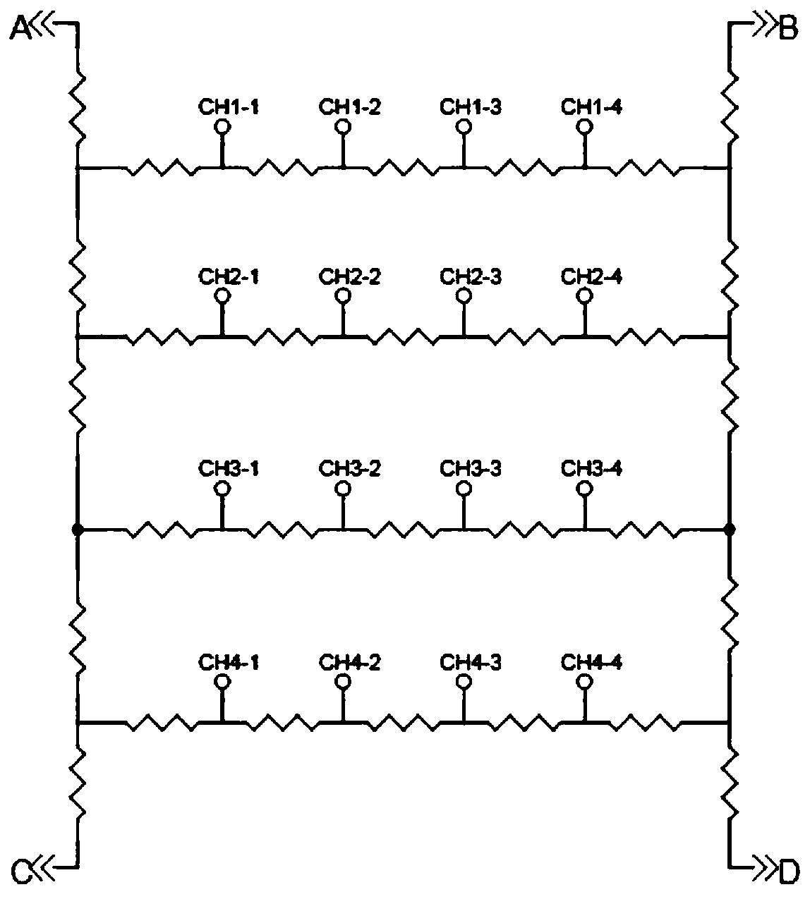
[0041] Step S2: The electric pulse signal obtained in step S1 is transmitted to the resistance network, and the resistance network integrates the input electric pulse signal into four output electric pulse signals, and the four output electric pulse signals pass through four front The preamplifier is sent to the pulse shape analysis system to obtain four channels of pulse shape information.

[0042]Step S3: Perform the first correction on the four channels of pulse shape information obtained in step S2, respectively, to obtain the four channels of pulse shape information after the first correction.

[0043] Step S4: Calculate the area of ...

Embodiment 2

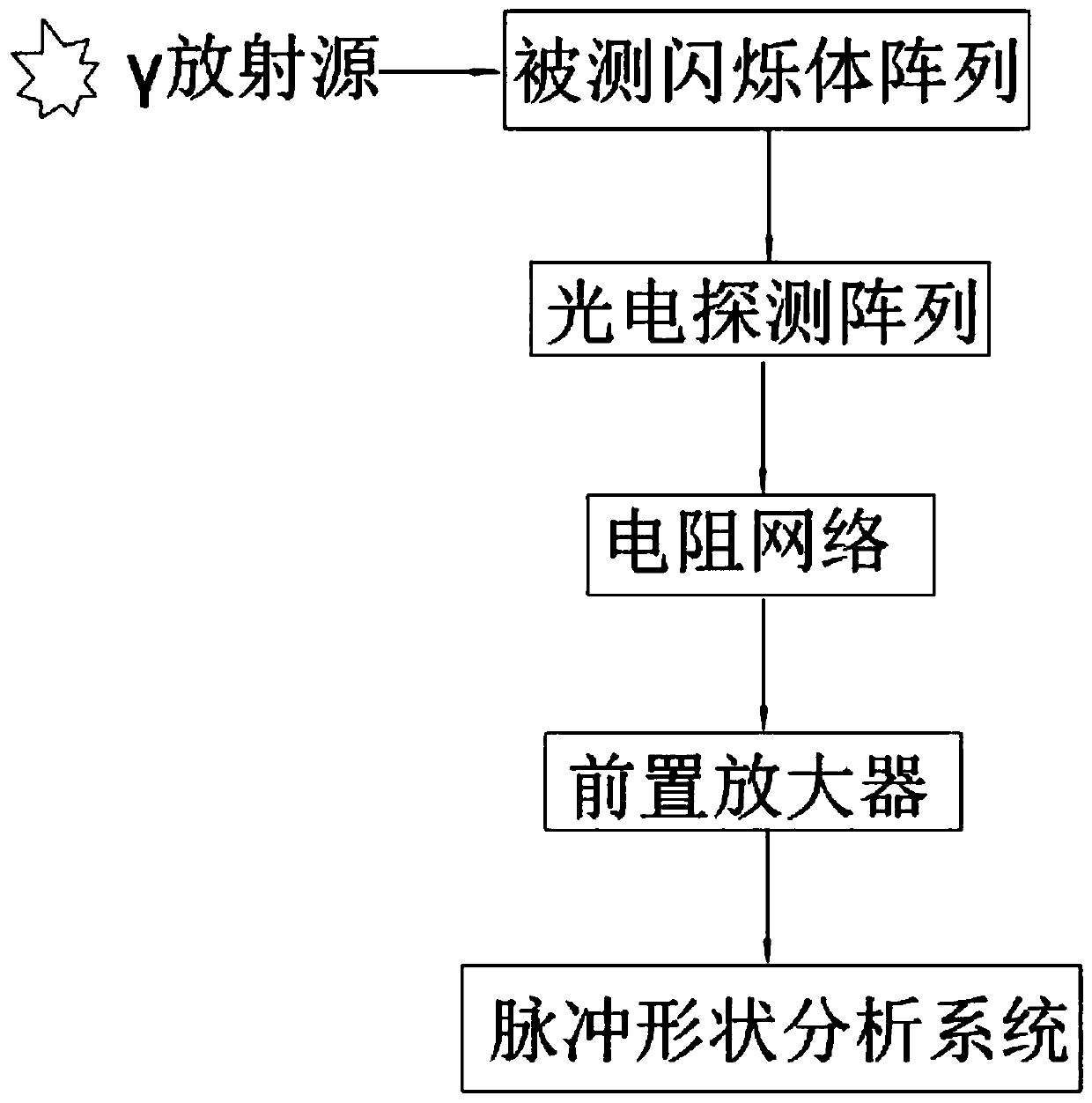
[0057] A kind of test device of scintillator array luminescence decay time designed according to the method described in embodiment 1, such as figure 1 As shown, it includes a photodetector array connected in sequence, a resistor network, a preamplifier and a pulse shape analysis system. When the scintillator array under test emits light, the photodetector array receives the light emitted by the scintillator array under test, and then converts the The optical signal is converted into an electrical pulse signal and sent to the resistor network, and the resistor network sends the electrical pulse signal to the preamplifier for signal amplification, and then the preamplifier sends the amplified electrical pulse signal to the pulse shape analysis system for electrical pulse signal information collection and analysis.

[0058] A test device for the luminescence decay time of a scintillator array of the present invention can simultaneously measure the relative light yield and lumine...

Embodiment 3

[0066] The present embodiment slightly differs as follows on the basis of the above-mentioned general scheme:

[0067] The scintillator array to be tested is a 15×15 LYSO scintillator array, and the luminescence decay time of each scintillator in the 15×15 LYSO scintillator array is obtained. Because LYSO has spontaneous radioactivity, no external radioactive source is used, so no need to set γ radioactive source.

[0068] Specifically, because the luminescence spectrum peak value of LYSO is 420nm, the photodetector array selects the square PMT multi-channel photomultiplier tube with 8×8 double-alkali photocathode and configures the corresponding light guide; the resistor network is composed of figure 2 The 4×4 signal input shown in is adaptively expanded to 8×8 signal input, and the test on the 15×15 LYSO scintillator array can be completed, and the same as in Example 1, let N=9, and finally Similarly, the outputs of 8×8 photodetectors are integrated into four outputs of A,...


PUM


Abstract

The invention relates to the technical field of radiation detectors, in particular to a method and device for testing luminescent decay time of a scintillator array. The method comprises the steps that a photodetection array receives a scintillation light emitted by the detected scintillator array and converts the light into an electrical pulse signal; the obtained electrical pulse signal is transmitted to a resistance network and integrated into output of four paths, and the electrical pulse signals output from the four paths are respectively sent to a pulse shape analysis system through fourpreamplifiers to obtain four-path pulse shape information; the obtained four-path pulse shape information is calculated to obtain the coordinate position of each scintillator illumination event and the luminescent decay time distribution of the scintillator before correction; the luminescent decay time is corrected to obtain the luminescent decay time distribution of each scintillator of the detected scintillator array. The method can be used for the light yield and time performance evaluation of the scintillator array, and greatly improve the test selection efficiency of the scintillator light yield and the luminescent decay time.

Description

technical field [0001] The invention relates to the technical field of radiation detectors, in particular to a method and device for testing the luminescence decay time of a scintillator array. Background technique [0002] In the field of radiation detectors, scintillator detectors are widely used in the detection fields of γ-rays, X-rays, β-rays, neutrons, and cosmic rays. Especially in nuclear medical instruments, the current mainstream SPECT and PET detectors all use scintillator detectors. [0003] As the core component of the scintillator detector, the performance of the scintillator itself, such as light yield and luminescence decay time (decaytime), has a fundamental impact on the final energy spectrum and time characteristics of the detector. For individual scintillators, there are many well-established methods to evaluate these properties. [0004] However, in modern radiation imaging detectors, especially PET detectors, scintillator arrays composed of dozens or ...

Claims


Application Information

Patent Timeline
Patent Type & Authority Patents(China)
IPC IPC(8): G01T1/202
CPCG01T1/202
Inventor 吴和宇郭维新
Owner JIANGSU SINOGRAM MEDICAL TECH CO LTD
Why Eureka
Try Eureka