Power conversion method and system for DC power transmission system

A direct current transmission system and power technology, applied in the direction of power transmission AC network, etc., can solve the problems of valve group pole power loss, valve group exit operation, etc., to achieve the effect of reducing machine cutting, reducing power loss and improving flexibility

Active Publication Date: 2019-03-19
GLOBAL ENERGY INTERCONNECTION RES INST CO LTD +2
View PDF7 Cites 0 Cited by
  • Summary
  • Abstract
  • Description
  • Claims
  • Application Information

AI Technical Summary

Problems solved by technology

[0005] In the DC transmission system, during the long-term operation of the converter, a certain valve group may fail or be out of operation due to maintenance. At this time, the power of the pole where the valve group is located will cause losses.

Method used


Image

  • Power conversion method and system for DC power transmission system
  • Power conversion method and system for DC power transmission system
  • Power conversion method and system for DC power transmission system

Examples


Embodiment 1

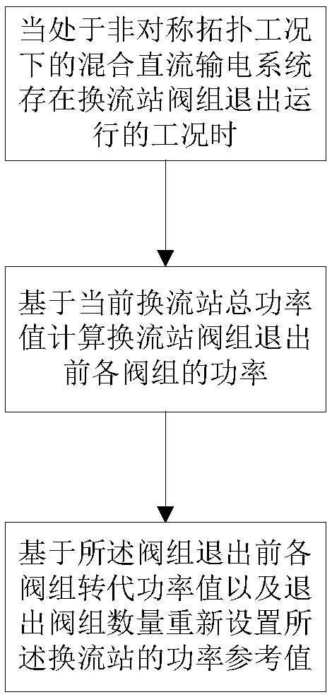
[0067] Step 1: When the hybrid direct current transmission system under asymmetric topology conditions has a working condition where the valve group of the converter station is out of operation:

[0068] Calculate the power of each valve group before the valve group of the converter station exits based on the total power value of the current converter station;

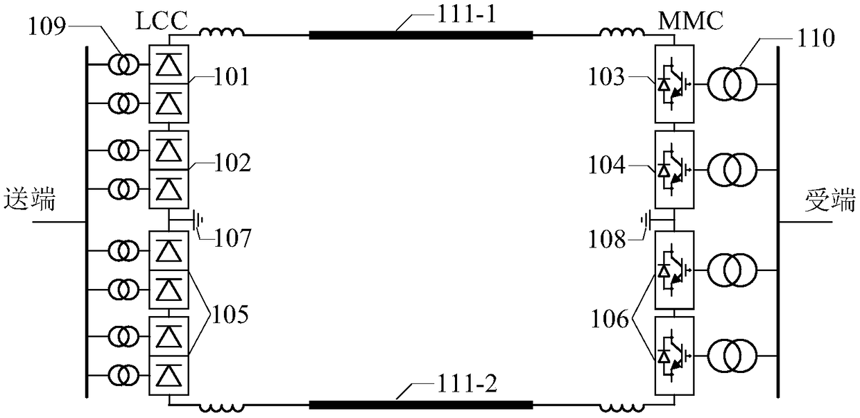
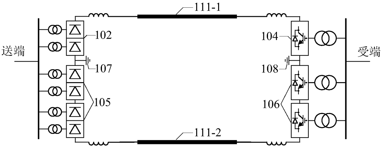
[0069] like figure 2 As shown, the DC system adopts a bipolar structure, in which the converter station at the sending end is LCC, and the converter station at the receiving end is MMC. Each pole of the converter station at the sending end is composed of two twelve-pulse LCCs connected in series. The LCC101 directly connected to the DC line 111-1 is a high-end valve group, and the LCC102 close to the ground electrode 107 is a low-end valve group; each twelve-pulse The pulse LCC is composed of two six-pulse LCCs connected in series, and each six-pulse LCC is connected to the AC grid through an AC transformer. Each po...

Embodiment 2

[0113] Based on the same inventive concept, the present invention also provides a DC transmission system power transfer system, the system includes:

[0114] Calculation module: used when the hybrid direct current transmission system under the condition of asymmetric topology has the condition that the valve group of the converter station is out of operation;

[0115] Calculate the power value of each valve group of the converter station based on the total power value of the current converter station, and calculate the transfer power value;

[0116] A setting module: configured to set a power reference value of the converter station based on the transfer power value.

[0117] The set modules include: a first determination submodule, a second determination submodule and a third determination submodule;

[0118] The first determination sub-module is used to determine the operation status of each pole of the converter station according to the number of exit valve groups;

[011...


PUM


Abstract

A power conversion method and system for a DC power transmission system are provided. The method comprises when a hybrid DC power transmission system in an asymmetric topology operating condition hasan operating condition in which a converter station valve group is out of operation, calculating the power of each valve group before the converter station valve group is out of operation based on atotal power value of the current converter station; and resetting the power reference value of the converter station based on the power of each valve group before the out of operation of the valve group and the number of the out-of-operation valve groups. The method and system improve the flexibility of system operation, minimize system power loss, reduces grid frequency changes, reduces generator tripping and load tripping.

Description

technical field [0001] The invention relates to the field of high-voltage direct current transmission, in particular to a power transfer method and system for a direct current transmission system. Background technique [0002] The high voltage direct current transmission technology (VSC-HVDC) based on the voltage source converter has been widely used in the field of direct current transmission. Compared with the high-voltage direct current transmission technology (LCC-HVDC) based on grid commutation converters, VSC-HVDC has compact structure, independent regulation of active and reactive power, no risk of commutation failure, black start capability, access to passive Or advantages such as weak AC systems. HVDC technology based on modular multilevel converter (MMC-HVDC) is an important way to realize VSC-HVDC. [0003] With the continuous maturity of MMC-HVDC technology, MMC-HVDC has entered the (±800kV) UHV level, which makes the interconnection of LCC-HVDC and MMC-HVDC po...

Claims


Application Information

Patent Timeline
Patent Type & Authority Applications(China)
IPC IPC(8): H02J3/36
CPCH02J3/36Y02E60/60
Inventor 李根安婷陆晶晶梁军蓝元良杨杰
Owner GLOBAL ENERGY INTERCONNECTION RES INST CO LTD
Why Eureka
Try Eureka