Limbs rehabilitation device for orthopedic patient

A rehabilitation device and technology for patients, applied in passive exercise equipment, physical therapy and other directions, can solve the problems of secondary injury of patients and high intensity of first-time healers, and achieve the effect of saving labor

Active Publication Date: 2019-03-22
何福友
View PDF14 Cites 1 Cited by
  • Summary
  • Abstract
  • Description
  • Claims
  • Application Information

AI Technical Summary

Problems solved by technology

[0004] However, most of the existing orthopedic rehabilitation training devices are driven by manpower, and there is a problem that the strength is too large for the first-time recoverers, and it is very easy to cause secondary injuries to the damaged parts of the patient, and there is a certain risk

Method used


Image

  • Limbs rehabilitation device for orthopedic patient
  • Limbs rehabilitation device for orthopedic patient
  • Limbs rehabilitation device for orthopedic patient

Examples


Embodiment 1

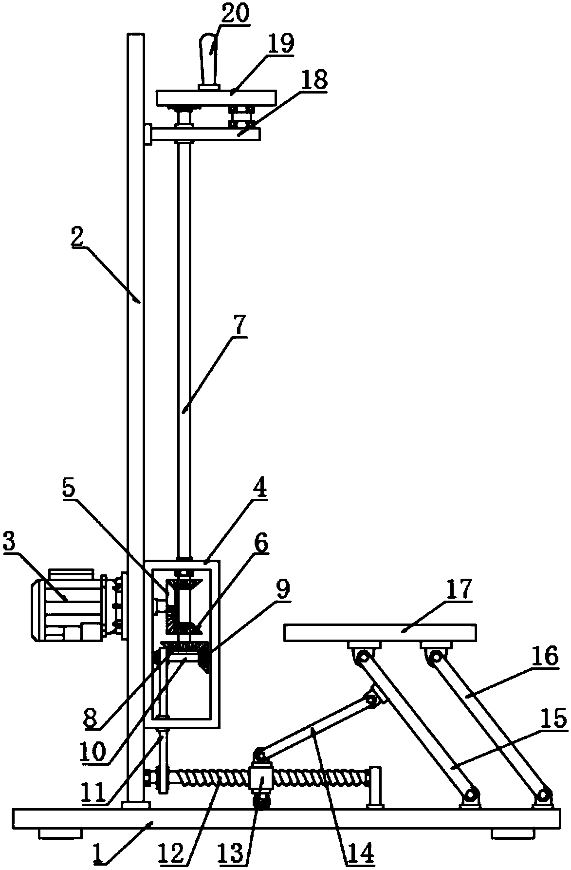
[0024] see Figure 1~3 , in an embodiment of the present invention, a limb rehabilitation device for orthopedic patients includes a support plate 1, a transmission box 4, a synchronous belt 11, an active swing bar 15 and a horizontal plate 17; 2. The front flange of the vertical plate 2 is fixedly connected to the drive motor 3, and the rear side of the vertical plate 2 is fixed with the transmission box 4. The drive motor 3 is electrically connected to the power supply and the control switch through a wire, and the output end of the drive motor 3 passes through the vertical plate 2 and the transmission box 4 and are connected in rotation with the two, the end of the output shaft of the driving motor 3 is fixed with a semi-conical gear 5, and pressing the control switch makes the driving motor 3 energized and then drives the output end to drive the semi-conical gear 5 to rotate; the semi-conical gear The upper and lower sides of the gear 5 are respectively provided with first ...

Embodiment 2

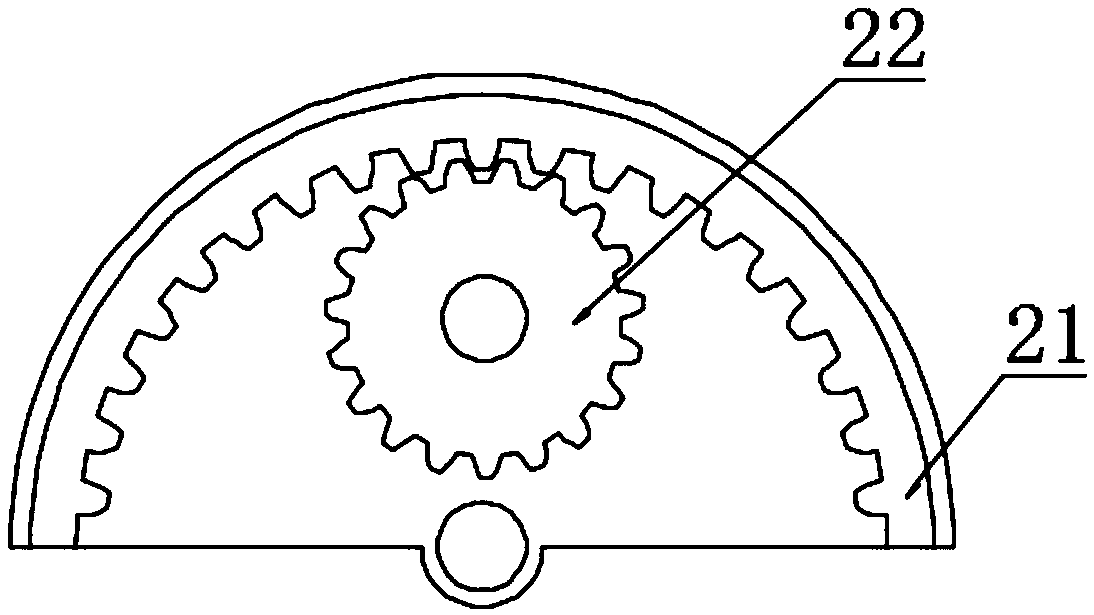
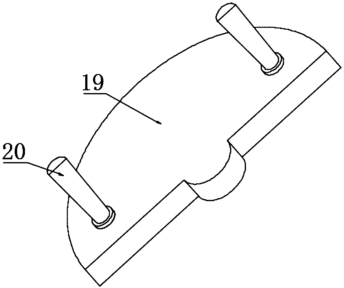
[0028] In order to further explain the above-mentioned limb rehabilitation device for orthopedic patients, this application provides another embodiment. The limb rehabilitation device for orthopedic patients in this embodiment has the following technical features: the upper end of the drive shaft 7 is fixedly connected to the gear 22, the gear 22 meshes with the inner gear ring 21, the inner gear ring 21 is fixedly fitted under the turntable 19, the turntable 19 is rotatably connected to the fixed table 18, and the two sides above the turntable 19 are symmetrically fixed with handrails 20, further, the turntable 19 is The semi-circular disk body, the reciprocating positive and negative driving shaft 7 drives the gear 22 to follow the reciprocating positive and negative rotation, the gear 22 drives the inner gear ring 21 and the turntable 19 to follow the reciprocating positive and negative rotation, and then drives the armrest 20 to follow the reciprocating rotation, and the pat...


PUM


Abstract

The invention discloses a limbs rehabilitation device for an orthopedic patient, particularly relates to an orthopedic patient early-healing rehabilitation exercise device and aims to solve the technical problem that injury recurrence may be caused due to the fact that knees of an early-healing patient are obviously stressed excessively by squatting motion as most existing rehabilitation equipmentneeds patients themselves to apply force for exercise. A screw and a gear are driven at the same time to be in reciprocating forward-backward rotation by a driving shaft in reciprocating forward-backward rotation, a sleeving block is driven to move forwards and backwards by the screw through a second bevel gear and a third bevel gear which have a great transmission ratio, the sleeving block drives a swing rod to drive a transverse plate to swing up and down to realize a function of training lower limbs of a patient, and the patient does not need to apply force, so that labor is saved, and needs on rehabilitation of the orthopedic patient are met better; the gear drives an inner tooth ring to drive a turnplate and an armrest to be in reciprocating small-amplitude swinging to exercise lumber vertebra of the patient for recovery, so that efficacy of whole-body exercise recovery is realized.

Description

technical field [0001] The invention relates to a rehabilitation device, in particular to a limb rehabilitation device for orthopedic patients. Background technique [0002] With the changes of the times and society, the spectrum of orthopedic injuries has changed significantly. For example, bone and joint tuberculosis, osteomyelitis, polio and other diseases have decreased significantly, traumas caused by traffic accidents have increased significantly, the aging of the population, senile bone Fractures and orthopedic arthropathy caused by porosity have increased, and the impact of environmental factors has led to a corresponding increase in bone tumors and rheumatoid arthritis. [0003] Orthopedic patients often need to take appropriate amount of activities to relieve each bone joint after initial recovery. Since the damaged part cannot perform regular exercise during the injury period, long-term static will cause slow movement of each bone joint and various discomforts. Th...

Claims


Application Information

Patent Timeline
IPC IPC(8): A61H1/02
CPCA61H1/0214A61H1/0237A61H1/0292A61H2205/08A61H2205/10
Inventor 何福友
Owner 何福友
Why Eureka
Try Eureka