Environment-friendly purifying device for waste gas in waste-plastic recycling

A technology for waste plastics and purification devices, which can be used in combination devices, chemical instruments and methods, and dispersed particle separation, etc., and can solve problems such as polluting the ecological environment, surrounding residents, and health and safety hazards.

Inactive Publication Date: 2019-03-22
界首市荣发再生资源有限公司
View PDF13 Cites 3 Cited by
  • Summary
  • Abstract
  • Description
  • Claims
  • Application Information

AI Technical Summary

Problems solved by technology

[0003] During the recycling and granulation of waste plastics, when the temperature exceeds 200°C, the plasticizer and its internal low-boiling impurities will be oxidized and decomposed, and the waste gas produced mainly includes dust, aromatics, amines, hydrogen

Method used


Image

  • Environment-friendly purifying device for waste gas in waste-plastic recycling
  • Environment-friendly purifying device for waste gas in waste-plastic recycling
  • Environment-friendly purifying device for waste gas in waste-plastic recycling

Examples


Embodiment 1

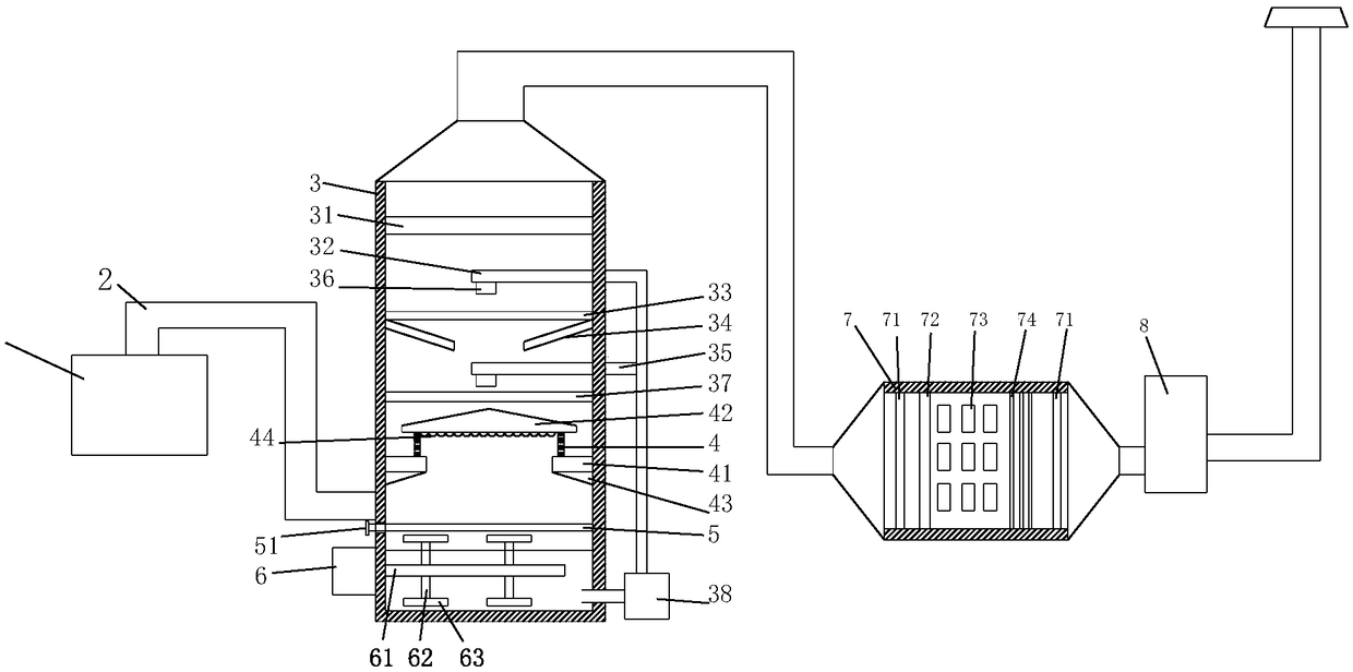
[0027] Such as Figure 1 to Figure 8 As shown, the present invention provides a waste gas treatment device for a waste plastic recycling system, comprising a gas collection hood 1, a purification box 3 and a treatment box 7, the gas collection hood 1 communicates with the bottom side of the purification box 3 through a gas delivery pipe 2,

[0028] The inner wall of the purification box 3 is provided with a baffle ring 41 corresponding to the top of the gas delivery pipe 2, and the upper surface of the baffle ring 41 is provided with a flow-limiting pipe 4. The surface of the flow-limiting pipe 4 is uniformly provided with through holes 401, and the top of the flow-limiting pipe 4 is covered with Baffle plate 42, and restrictor tube 4 is arranged on the inner side of baffle plate 42, the lower surface of retaining ring 41 is provided with diversion plate 43, and the inner wall of purification box 3 is provided with slide rail relatively below the corresponding diversion plate 4...

Embodiment 2

[0035] Such as Figure 1 to Figure 8 As shown, the present invention provides a waste gas treatment device for a waste plastic recycling system, comprising a gas collection hood 1, a purification box 3 and a treatment box 7, the gas collection hood 1 communicates with the bottom side of the purification box 3 through a gas delivery pipe 2,

[0036] The inner wall of the purification box 3 is provided with a baffle ring 41 corresponding to the top of the gas delivery pipe 2, and the upper surface of the baffle ring 41 is provided with a flow-limiting pipe 4. The surface of the flow-limiting pipe 4 is uniformly provided with through holes 401, and the top of the flow-limiting pipe 4 is covered with baffle 42, and the restrictor pipe 4 is arranged on the inner side of the baffle 42, the lower surface of the retaining ring 41 is provided with a baffle 43, and the inner wall of the purification box (3) corresponds to the bottom of the baffle (43) A slide rail is oppositely provided...


PUM


Abstract

The invention discloses a waste-gas treating device of a waste-plastic recycling system. The waste-gas treating device comprises a gas collecting hood, a purifying box and a treating box, wherein thegas collecting hood is communicated with the bottom side of the purifying box by a gas delivery pipe; the inner wall of the purifying box, corresponding to a part above the gas delivery pipe, is provided with a blocking ring; a flow-limiting pipe is arranged on the upper surface of the blocking ring; through holes are uniformly formed in the surface of the flow-limiting pipe; a baffle plate is arranged at the top part of the flow-limiting pipe in a covering manner, and the flow-limiting pipe is arranged at the inner side of the edge of the baffle plate; a circulating water pump is arranged atthe outer side of the bottom part of the purifying box; one end of the circulating water pump is communicated with the bottom part in the purifying box by a pipeline. The waste-gas treating device disclosed by the invention has the beneficial effects that by arrangement of the baffle plate and a flow-limiting plate, waste gas passes through a flow-limiting drum to reach the bottom part of the baffle plate; convex blocks at the bottom part of the baffle plate can adsorb particles in the waste gas.

Description

Technical field: [0001] The invention relates to a waste gas treatment device, in particular to an environmental protection purification device for waste plastic regenerated waste gas. Background technique: [0002] With the improvement of people's living standards, a large amount of plastic waste is produced every day, and these wastes have high recycling value. Recycling waste plastics is an environmentally friendly and economical approach. At this stage, my country's waste plastic recycling technology is still dominated by physical recycling. The recycling process mainly includes collection, classification and separation, cleaning, drying, crushing and granulation, and is modified and reprocessed to make products suitable for market demand or mixed with new materials. use. [0003] During the recycling and granulation of waste plastics, when the temperature exceeds 200°C, the plasticizer and its internal low-boiling impurities will be oxidized and decomposed, and the was...

Claims


Application Information

Patent Timeline
IPC IPC(8): B01D53/32B01D50/00B01D53/00B01D53/74B01D53/75
CPCB01D50/00B01D53/007B01D53/323B01D53/74B01D53/75
Inventor 刘新安姜永俊
Owner 界首市荣发再生资源有限公司
Why Eureka
Try Eureka