Offshore platform automation workover machine upper tube manipulator
A technology for offshore platforms and manipulators, applied to manipulators, drill pipes, casings, etc., can solve problems such as danger, low efficiency, and manipulators that cannot meet needs, and achieve the effects of good safety, simple and reliable structure, and improved work efficiency
- Summary
- Abstract
- Description
- Claims
- Application Information
AI Technical Summary
Problems solved by technology
Method used
Image


Examples
Embodiment Construction
[0016] The present invention will be specifically described below in conjunction with the accompanying drawings and embodiments.
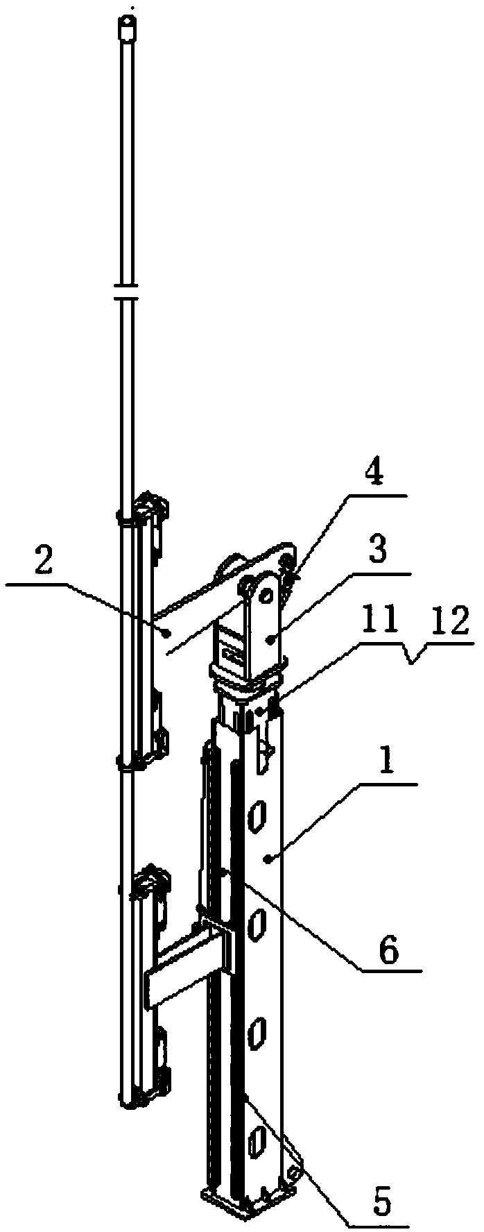
[0017] figure 1 Shown is the structural representation of the present invention.
[0018] The present invention provides a pipe-loading manipulator for an automatic workover rig on an offshore platform, which includes a main arm 1 and a manipulator device 2, a top end seat 3 is provided on the top of the main arm 1, a rotary oil cylinder 4 is arranged inside the top end seat 3, and the main arm 1 There are slide rails 5 and lifting cylinders 6 on the back; two manipulator devices 2 are provided, one of which is hinged on the top seat 2 of the main arm 1 through a hinge shaft to form a rotating manipulator, and the rotating manipulator passes through the rotating oil cylinder 3 The control can rotate 180° around the top seat 3 and push the oil pipe 7 into the derrick; another manipulator device 2 is installed on the slide rail 5 on the back of the ...
PUM
 Abstract
Description
Claims
Application Information
PatSnap Eureka turns technology decisions into work you can execute. Powered by our Innovation Knowledge Graph, it runs expert workflows across engineering, life sciences, materials and intellectual property. Get your review-ready output in minutes.


