Blade locking device applied to wind electricity typhoon unit

A locking device and typhoon technology, which is applied in the control of wind turbines, wind power generation, wind turbines, etc., can solve the problems that the locking pin is easy to fall off, it is difficult to meet the strength requirement, and the locking angle is not fixed, so as to solve the structural form and size restrictions, meet the structural design requirements, and reduce the effect of installation space

Active Publication Date: 2019-03-22
SHANGHAI ELECTRIC WIND POWER GRP CO LTD
View PDF10 Cites 4 Cited by
  • Summary
  • Abstract
  • Description
  • Claims
  • Application Information

AI Technical Summary

Problems solved by technology

Disadvantages: The locking angle is not fixed through the engagement of the locking pin and the blade bearing gear. Misoperation may also occur when the blade rotation angle is inaccurate. The diameter of the locking pin is limited by the pitch of the teeth, which is difficult to reach under typhoon conditions. Locking Strength Requirements
Disadvantages: The blade locking device is fixed on the blade root bolt, and the blade and the hub are fixed by the bolt. It is necessary to lengthen the blade root bolt and cut a groove at the corresponding position of the hub
For ty

Method used


Image

  • Blade locking device applied to wind electricity typhoon unit
  • Blade locking device applied to wind electricity typhoon unit
  • Blade locking device applied to wind electricity typhoon unit

Examples


Embodiment Construction

[0023] The present invention will be further described below through specific embodiments in conjunction with the accompanying drawings. These embodiments are only used to illustrate the present invention, and are not intended to limit the protection scope of the present invention.

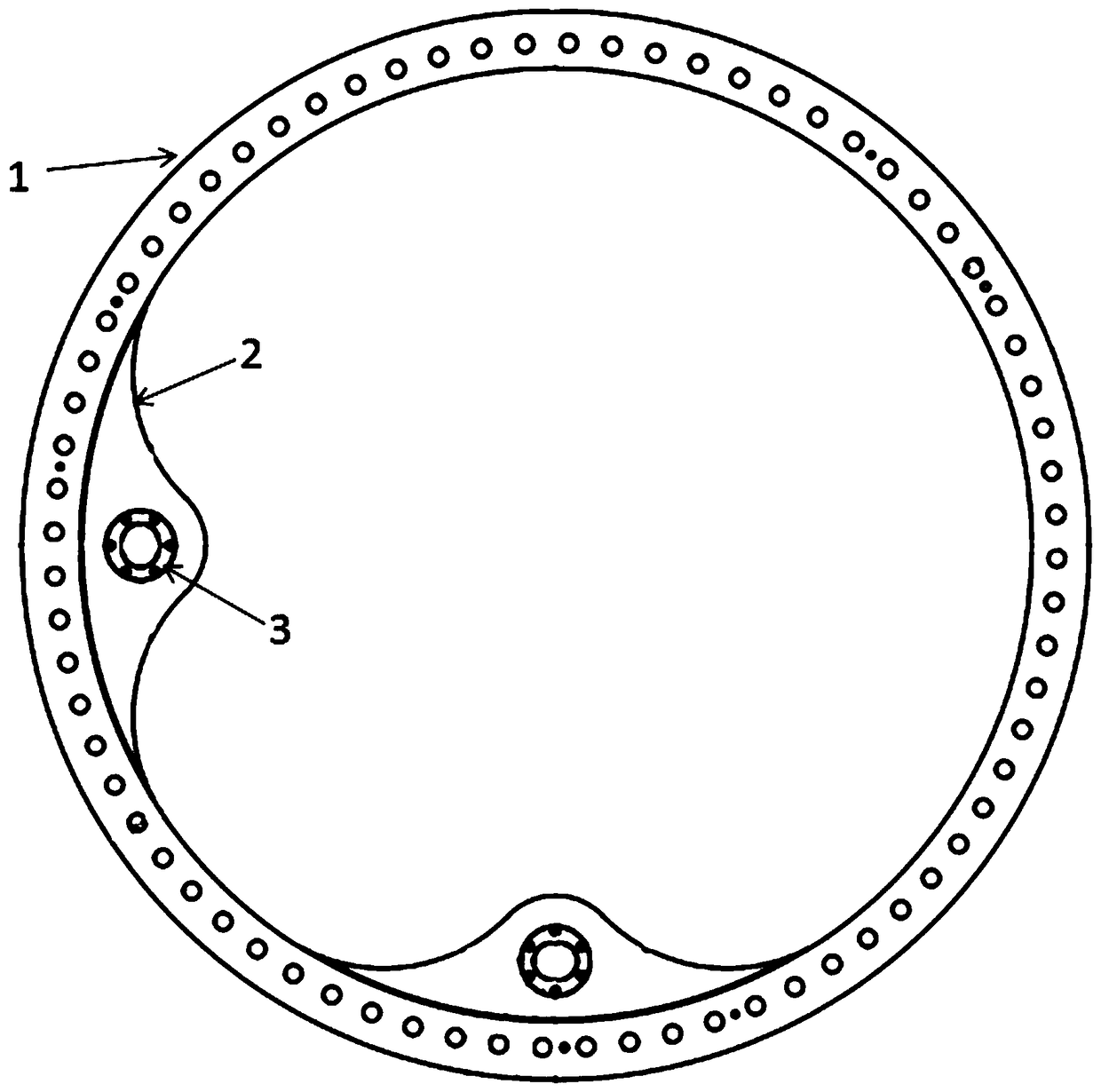
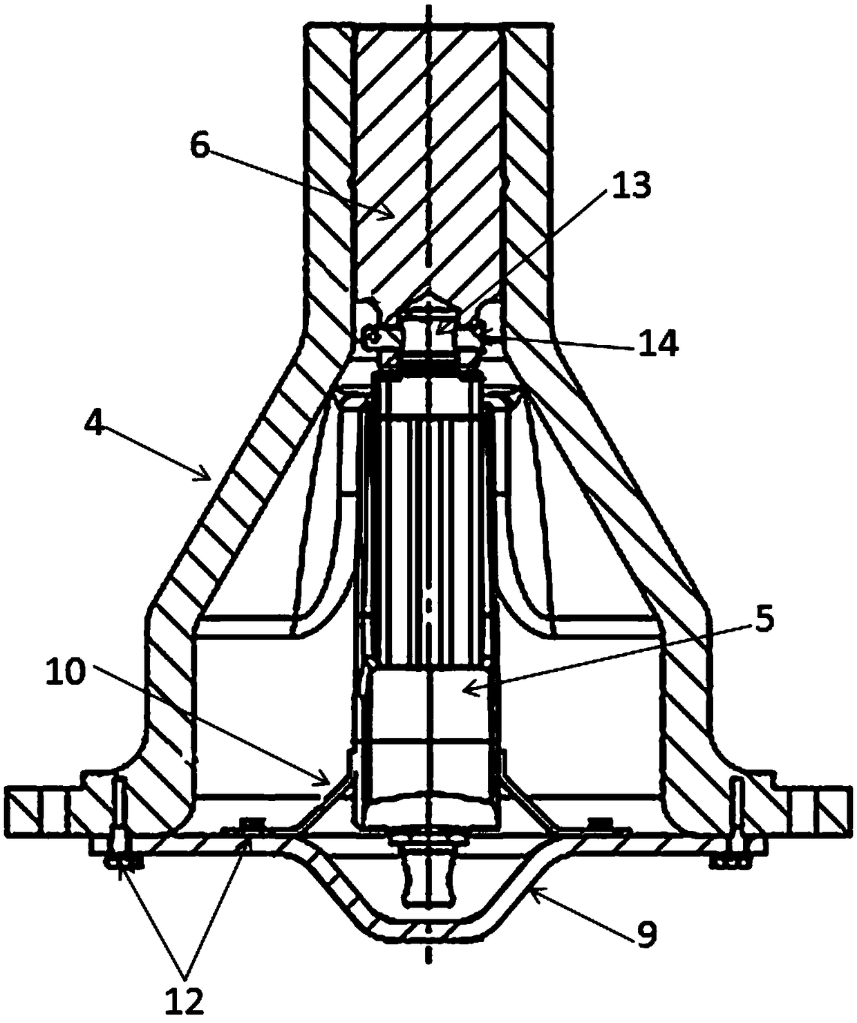
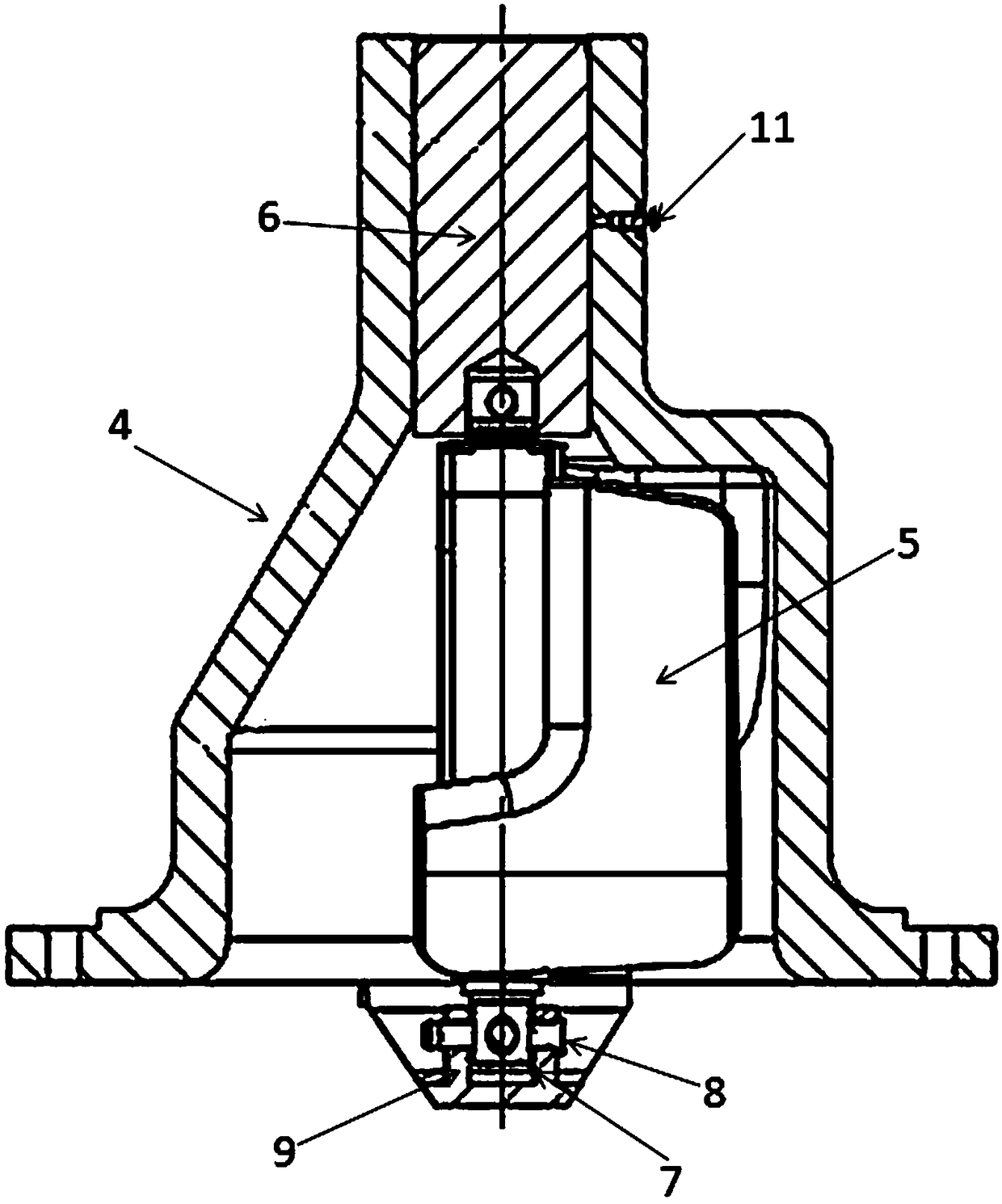
[0024] Such as Figure 1 to Figure 5 As shown, the present invention provides a blade locking device applied to a wind power generator set, which includes a locking disc 1 and an electric locking mechanism.

[0025] The locking disc 1 is installed between the blade bearing and the blade root of the fan unit of the wind station; the main body of the locking disc 1 is ring-shaped, and the inner edge of the ring is provided with a raised part 2 extending toward the center of the circle; A shaft sleeve 3 is installed in the through hole; the shaft sleeve 3 has a flange edge, and a circle of countersunk holes is arranged on the flange edge, and the shaft sleeve 3 is connected with the boss 2 with screw...


PUM


Abstract

The invention discloses a blade locking device applied to a wind electricity typhoon unit. The blade locking device applied to the wind electricity typhoon unit includes a locking plate and an electric locking mechanism, wherein the locking plate is installed between a blade bearing of the wind electricity typhoon unit and blade roots of the wind electricity typhoon unit, the main body of the locking plate is in a ring shape, a protrusion part extending to the direction of the circle center is arranged on the inner edge of the ring-shaped locking plate, the protrusion part is provided with a shaft sleeve, the electric locking mechanism includes a guide seat mounted on a hub web plate of the wind electricity typhoon unit and an electric push rod arranged in the guide seat, a guide hole is formed in the top end of the guide seat, and a fitting pin connected with the electric push rod in a drive mode is arranged in the guide hole; and when the blades are locked, the electric push rod pushes the fitting pin into the shaft sleeve of the locking plate. The blade locking form of the blade locking device is used for the wind electricity typhoon unit and capable of achieving higher lockingstrength, and the blade locking purpose is achieved effectively, safely and quickly under the complex and severe wind regime condition.

Description

technical field [0001] The invention relates to the technical field of blade locking, in particular to a blade locking device applied to a fan unit of a wind power station. Background technique [0002] The existing domestic blade locking devices are usually in the form of manual locking or hydraulic locking, which are fixed by bolts or locking pins, and the blade bearings or blade roots are directly connected to the hub. [0003] Commonly used structure 1: the blade locking device is installed on the hub, the locking pin is connected to the main body of the locking device through a fixing bolt, and braked by the engagement of the locking pin and the blade bearing gear. Disadvantages: The locking angle is not fixed through the engagement of the locking pin and the blade bearing gear. Misoperation may also occur when the blade rotation angle is inaccurate. The diameter of the locking pin is limited by the pitch of the teeth, which is difficult to reach under typhoon condition...

Claims


Application Information

Patent Timeline
IPC IPC(8): F03D7/04F03D80/00
CPCF03D7/0244F03D7/0268F03D7/042F03D80/00Y02E10/72
Inventor 王冰李红梅李顺利
Owner SHANGHAI ELECTRIC WIND POWER GRP CO LTD
Why Eureka
Try Eureka