High-gain broadband horn antenna

A broadband horn, high gain technology, applied in the direction of antenna, waveguide horn, antenna grounding switch structure connection, etc., can solve the problem of inability to effectively suppress electromagnetic wave radiation, inability to effectively control standing waves, etc., to achieve good radiation effect, good low-frequency characteristics, The effect of reducing the standing wave ratio

Pending Publication Date: 2019-03-22
安徽站乾科技有限公司
View PDF0 Cites 7 Cited by
  • Summary
  • Abstract
  • Description
  • Claims
  • Application Information

AI Technical Summary

Problems solved by technology

However, when the existing ultra-wideband horn antenna is used for microwave testing or microwave application, it cannot satisfy all frequency bands with good voltage standin...

Method used


Image

  • High-gain broadband horn antenna
  • High-gain broadband horn antenna
  • High-gain broadband horn antenna

Examples


Embodiment Construction

[0016] The technical solution of the present invention will be further described in detail below in conjunction with the accompanying drawings, but the protection scope of the present invention is not limited to the following description.

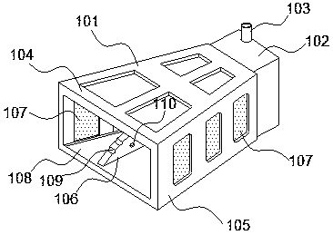
[0017] A high-gain broadband horn antenna, see appendix figure 1 As shown, it includes a square horn 101, a waveguide 102 and a coaxial connector 103. The square horn 101 is connected to the waveguide 102, and the waveguide 102 is detachably connected to the coaxial connector 103; The upper ridge and the lower ridge 106; the speaker shell is a rectangular horn structure 108 formed by splicing a pair of narrow metal walls 105 and a pair of wide metal walls 104. The upper ridge and the lower ridge 106 are respectively arranged on the wide metal wall 104, The ends of the upper and lower ridges 106 near the feeding point are circular arc structures, and the ends of the upper and lower ridges 106 near the opening of the horn housing are provided...


PUM


Abstract

The invention discloses a high-gain broadband horn antenna. The high-gain broadband horn antenna includes a square horn, a waveguide and a coaxial connector, wherein the square horn is connected withthe waveguide; the waveguide and the coaxial connector are detachably connected; the square horn includes a horn housing, an upper ridge and a lower ridge; the upper ridge and the lower ridge are arranged in the horn housing; the horn housing is a rectangular horn structure which is formed through mutual splicing of a pair of narrow-surface metal walls and a pair of wide-surface metal walls; the upper ridge and the lower ridge are arranged on the wide-surface metal walls; one end, of each of the upper ridge and the lower ridge, close to a feeding point, is an arc structure; one end, of each ofthe upper ridge and the lower ridge, close to the opening of the horn housing, is provided with a plurality of rippled grooves; and the waveguide is a rectangular waveguide structure with a cavity. For the high-gain broadband horn antenna, by setting a plurality of rectangular holes on the narrow-surface metal walls, the antenna can obtain better low frequency characteristic while no deviation occurs on a high frequency radiation directional diagram; and due to the curve structure of the ridge body of the high-gain broadband horn antenna, the standing-wave ratio of the antenna can be reduced,and better radiation effect can be obtained.

Description

technical field [0001] The invention relates to the technical field of radio frequency antennas, in particular to a high-gain broadband horn antenna. Background technique [0002] With the development of microwave communication technology, ultra-wideband antenna equipment has attracted much attention, and has been widely used in the field of transient electromagnetic fields such as broadband communication, spread spectrum communication, ground penetrating radar, and electromagnetic compatibility. However, the existing ultra-wideband horn antennas cannot satisfy all frequency bands with good voltage standing wave ratio and radiation pattern when performing microwave testing or microwave applications, and cannot effectively suppress the radiation of backward electromagnetic waves and effectively control standing waves. Contents of the invention [0003] The purpose of the present invention is to overcome the deficiencies of the prior art and provide a high-gain broadband hor...

Claims


Application Information

Patent Timeline
IPC IPC(8): H01Q13/02H01Q1/50
CPCH01Q1/50H01Q13/0275
Inventor 汪文清张立生陈浩
Owner 安徽站乾科技有限公司
Why Eureka
Try Eureka