Pulley device for reducing friction of paying-off construction

A technology of friction force and pulley, which is applied in the direction of overhead line/cable equipment, etc., can solve the problems of wire and lead rope sheath damage loss, increase the damage of traction broken rope pulley, increase the safety risk of power transmission construction, etc., and achieve the reduction of construction safety risk, Increased passability and protection, reduced damage

Inactive Publication Date: 2019-03-22
TIANJIN ELECTRIC POWER TRANSMISSION & TRANSFORMATION ENG CORP +2
View PDF6 Cites 0 Cited by
  • Summary
  • Abstract
  • Description
  • Claims
  • Application Information

AI Technical Summary

Problems solved by technology

[0003] At present, in the construction of overhead transmission lines, when the guide ropes, traction ropes and conductors are deployed, it often occurs that these traction ropes, conductors and the pulleys in the construction sliders on the tower do not rotate synchronously (the rotation of the pulley itself is affected by the diameter of the pulley, Due to friction problems caused by factors such as self-weight and internal bearing damage), some pulleys even cannot rotate in the air (self-wheel body, bearing damage, damage) (temporary replacement of pulleys in the air is complicated), direct wires The friction between the pulley and the pulley is the largest (even if the pulley is glued), which directly causes the loss and damage of the wire, guide rope, traction rope (wire rope), and pulley, and increases the traction force in the overall pay-off. This friction directly causes the wire , lead rope sheath damage, loss, and even increase the risk of traction broken rope (wire rope), broken wire (conductor, ground wire), and pulley damage, which increases the safety risk of power transmission construction

Method used


Image

  • Pulley device for reducing friction of paying-off construction
  • Pulley device for reducing friction of paying-off construction
  • Pulley device for reducing friction of paying-off construction

Examples


Embodiment Construction

[0017] The present invention will be further described in detail below in conjunction with the accompanying drawings and through specific embodiments. The following embodiments are only descriptive, not restrictive, and cannot limit the protection scope of the present invention.

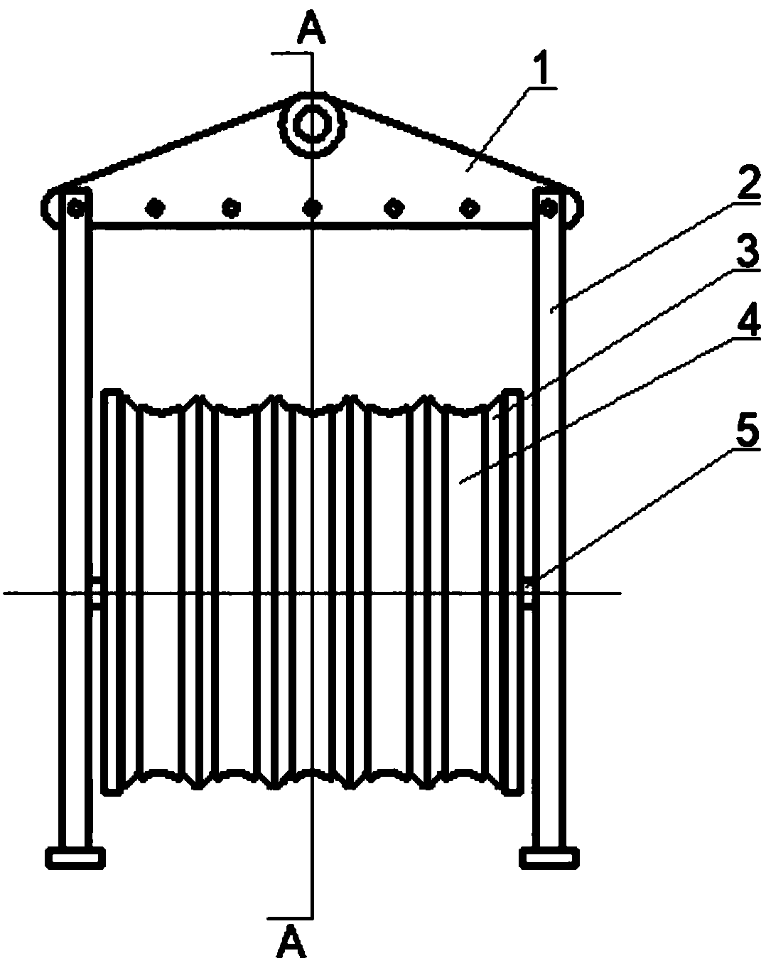
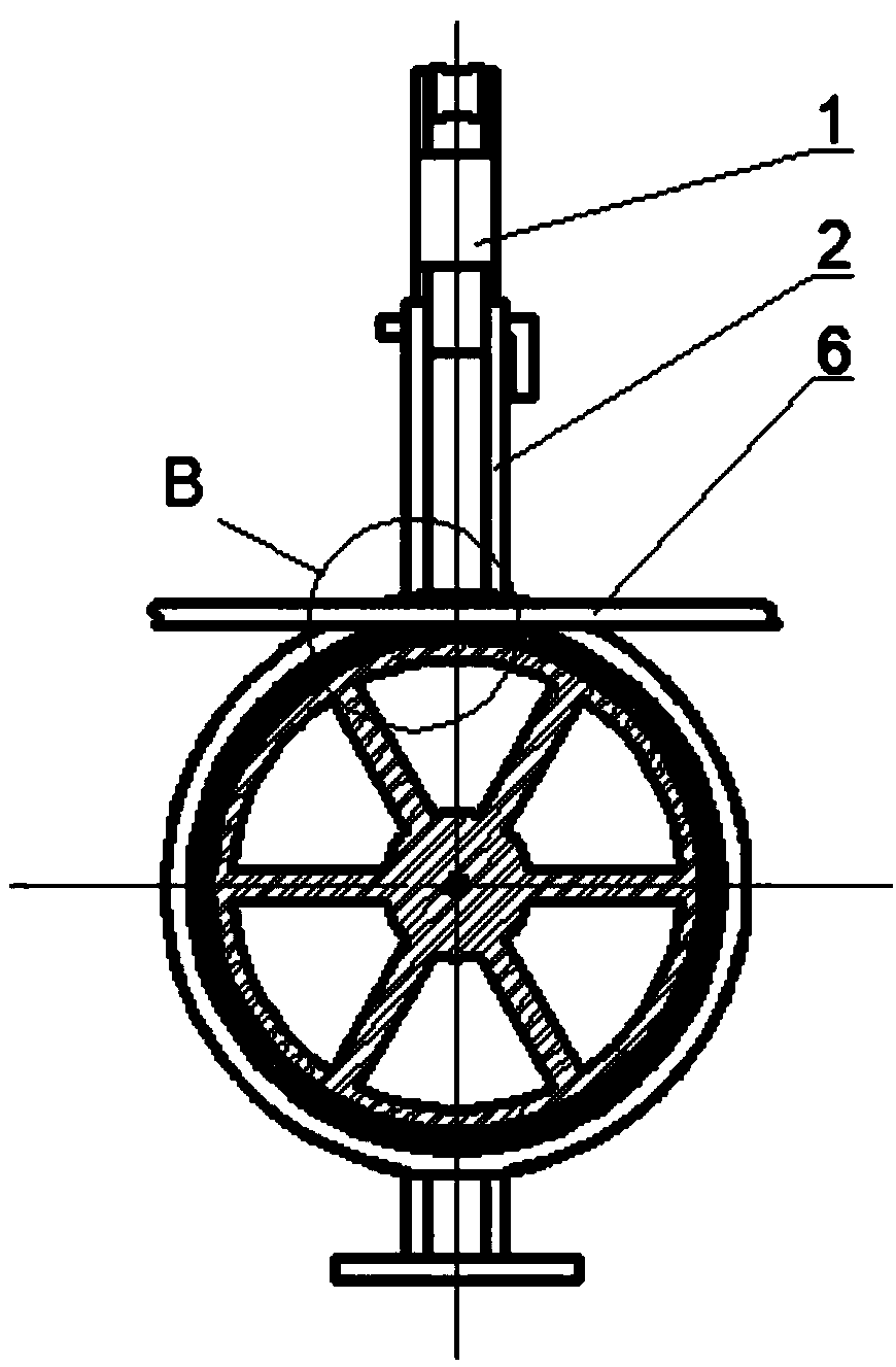
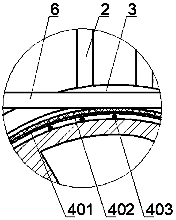
[0018] A pulley device for reducing friction in setting out construction, including a hoisting plate 1, a hanger 2, a main shaft 5, a pulley 3 and a ferrule 4, hangers 2 are symmetrically installed on both sides of the lower end of the hoisting plate, and in the middle of the hangers on both sides A main shaft 5 is installed, and a plurality of pulleys 3 are mounted coaxially and side by side on the main shaft. An annular groove is formed on the outer circumference of the pulley, and a set of rings 4 is set in the annular groove, and the ring is carried out in the groove of the pulley. Flexible rotation, the wire 6 or the traction rope passing through the pulley is erected on the ferrule, thereby prev...


PUM


Abstract

The invention relates to a pulley device for reducing friction of paying-off construction. The pulley device comprises a lifting plate, lifting frames, a main shaft, pulleys and ferrules, wherein bothsides of the lower end of the lifting plate are symmetrically provided with the lifting frames, a main shaft is mounted in the middle parts of the lifting frames on two sides, a plurality of the pulleys are threaded on the main shaft coaxially side by side, an annular groove is formed in the outer circumference of each pulley, one ferrule is sleeved in the corresponding annular groove, the ferrules can rotate in the grooves of the pulleys, and the lifting plate is erected on the ferrules by means of lead wires or traction ropes of the pulleys. The pulley device can effectively improve the construction efficiency, is not affected by the self-weight and damage degrees of the pulleys, is convenient to install and disassemble, and significantly reduces the risk of damaging the pulleys, the operation risk and the construction safety risk. The pulley device further has the effects of being low in manufacturing cost, reusable, economical, beautiful and practical.

Description

technical field [0001] The invention belongs to the technical field of power transmission high-voltage power transmission line construction, and in particular relates to a pulley device for reducing the frictional force of line setting-out construction. Background technique [0002] The setting out construction operation is a very important part of the transmission line, which is related to the safe construction and engineering quality of the transmission line, and is related to the long-term safe operation of the power grid. [0003] At present, in the construction of overhead transmission lines, when the guide ropes, traction ropes and conductors are deployed, it often occurs that these traction ropes, conductors and the pulleys in the construction sliders on the tower do not rotate synchronously (the rotation of the pulley itself is affected by the diameter of the pulley, Due to friction problems caused by factors such as self-weight and internal bearing damage), some pul...

Claims


Application Information

Patent Timeline
Patent Type & Authority Applications(China)
IPC IPC(8): H02G1/02
CPCH02G1/02
Inventor 饶友平毕建全刘威赵斌曹正
Owner TIANJIN ELECTRIC POWER TRANSMISSION & TRANSFORMATION ENG CORP
Why Eureka
Try Eureka