Wedge-shaped tension clamp

A tension-resistant clamp and wedge-shaped technology, which is applied in the direction of adjusting/maintaining mechanical tension and cable suspension devices, can solve problems such as unreliable pressure, hydraulic tension clamp cracks, threats to safe operation of power transmission, etc., and achieves simple structure, Guaranteed grip effect

Pending Publication Date: 2019-03-22
BEIJING PLP CONDUCTOR LINE PRODS
View PDF0 Cites 2 Cited by
  • Summary
  • Abstract
  • Description
  • Claims
  • Application Information

AI Technical Summary

Problems solved by technology

[0003] At present, most of the domestic transmission lines are hydraulic tension clamps. The construction is cumbersome and requires special hydraulic pumps and hydraulic machines. The operation level of construction personnel is very high.
In the actual construction process, due to irregular operation, the hydraulic tension clamps have cracks or are not compacted, which seriously affect the performance of the hydraulic tension clamps and seriously threaten the safe operation of power transmission.

Method used


Image

  • Wedge-shaped tension clamp
  • Wedge-shaped tension clamp
  • Wedge-shaped tension clamp

Examples


Embodiment Construction

[0026] In order to clearly illustrate the design concept of the present invention, the present invention will be described below in conjunction with examples.

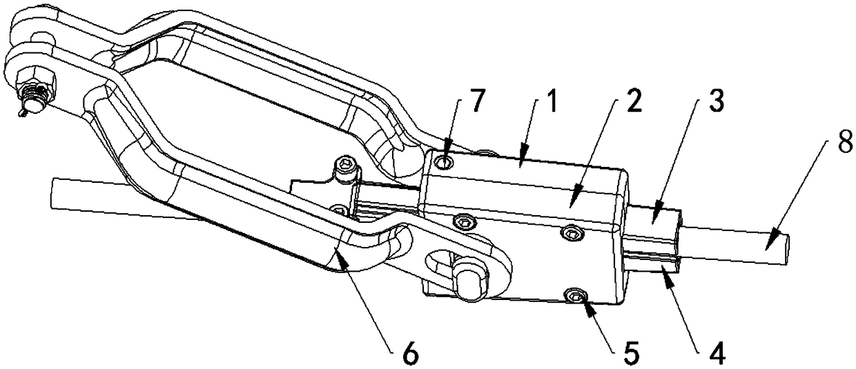
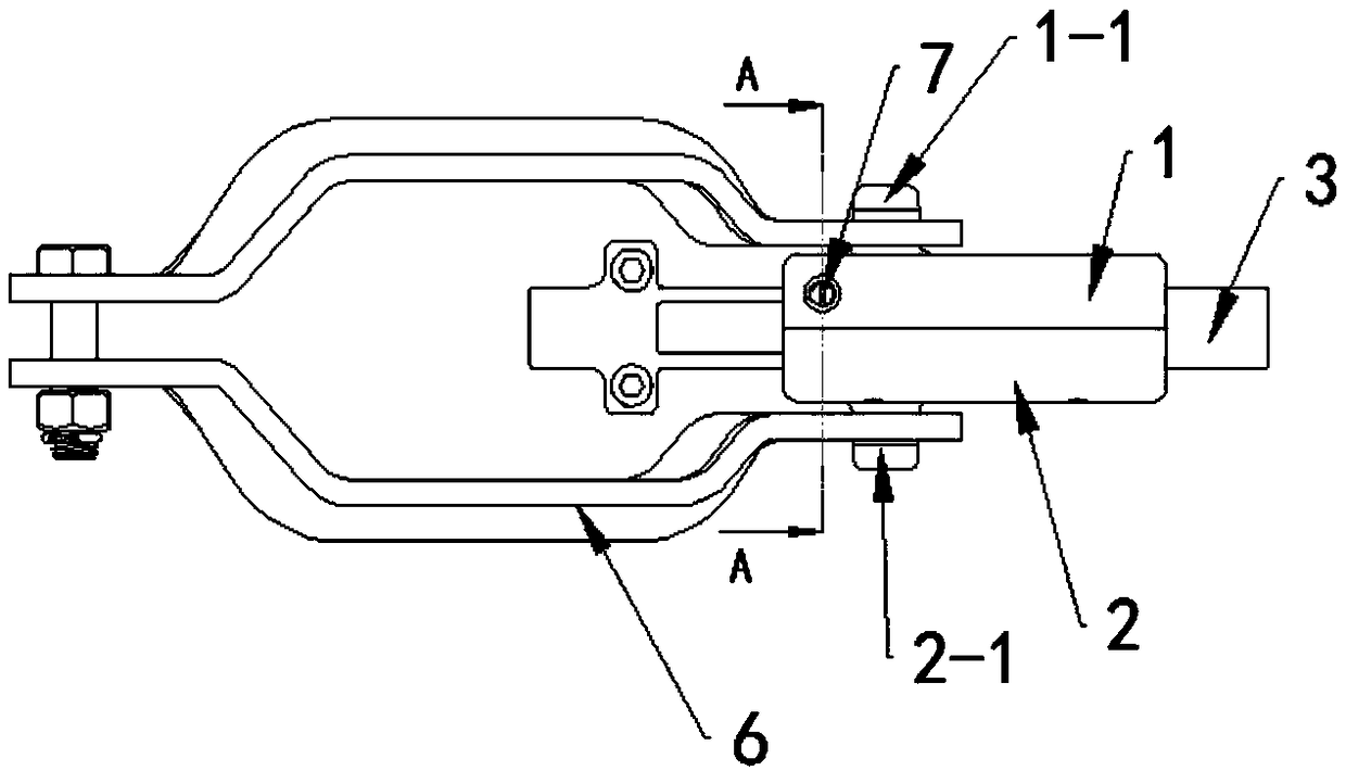
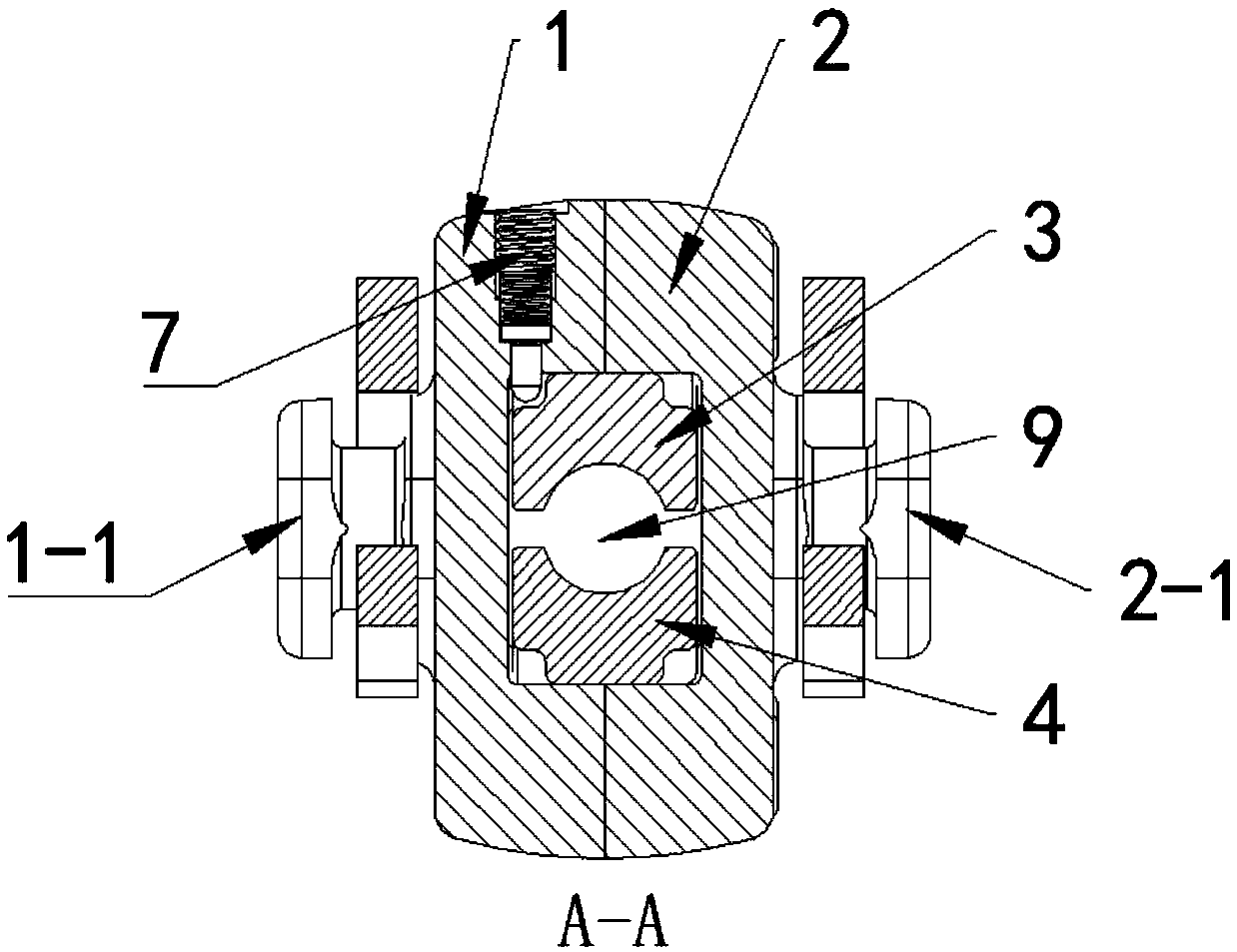
[0027] Such as Figure 1-3 In the example shown, the wedge-shaped strain clamp of the present invention includes: a positioning sheath 1, a sheath 2, an upper splint 3, a lower splint 4, a connecting plate 6 and a set of anti-off devices 7; wherein, the positioning sheath 1 and the mounting plane of the sheath 2 are connected by four screws 5 to form a wedge-shaped sheath with a wedge-shaped hole, the rectangular area of ​​the front cross-section of the wedge-shaped hole is larger than the rectangular area of ​​the rear cross-section; the upper splint 3 and the lower splint 4 are set through In the wedge-shaped hole, the corresponding surfaces of the upper splint 3 and the lower splint 4 are parallel, and the upper surface of the upper splint 3 and the lower surface of the lower splint 4 are respectively attached to th...


PUM


Abstract

The invention discloses a wedge-shaped tension clamp, which comprises a positioning sheath, a sheath, an upper clamping plate, a lower clamping plate, a connecting plate and a separation preventing device; the positioning sheath and the sheath are connected to form a wedge-shaped sheath with a wedge-shaped hole, and the rectangular area of the front end cross section of the wedge-shaped hole is larger than the rectangular area of the rear end cross section; the upper and lower clamping plates are arranged in the wedge-shaped hole in a penetrating manner, corresponding surfaces of the upper andlower clamping plates are parallel, and the upper surface of the upper clamping plate and the lower surface of the lower clamping plate are adhered to two wedge-shaped planes of the wedge-shaped holerespectively; arc-shaped grooves are correspondingly formed in the upper and lower clamping plates on the corresponding surfaces, and the corresponding arc-shaped grooves form a lead wire groove clamping a lead wire; the upper and lower clamping plates are fixedly connected to form a clamping plate assembly on the outer side of the wedge-shaped hole; and the positioning sheath is provided with aseparation preventing device for preventing the positioning sheath from being separated from the clamping plate assembly, and a separation preventing groove matched with the separation preventing device is formed in each of the upper and lower clamping plates. The wedge-shaped tension clamp is simple in structure, can be installed by using a common tool, and can prevent the clamping plate assemblyfrom sliding out of the wedge-shaped hole through the cooperation of the separation preventing device and the separation preventing grooves.

Description

technical field [0001] The invention relates to a strain clamp, in particular to a wedge-shaped strain clamp. Background technique [0002] When erecting cables, including railway cables, high-voltage cables, etc., tension clamps are required at the connection between the cable and the pylon or pole. The tension clamp is used to fix the conductor or lightning protection wire to the tension insulator string of the non-linear tower, and acts as an anchor, and is also used to fix the stay wire of the stay pole tower. Strain clamps are used for corners, splices, and terminal connections. [0003] At present, most of the domestic transmission lines are hydraulic strain clamps. The construction is cumbersome and requires special hydraulic pumps and hydraulic machines. The operation level of construction personnel is very high. In the actual construction process, due to irregular operation, the hydraulic tension clamps have cracks or are not compacted, which seriously affect the ...

Claims


Application Information

Patent Timeline
Patent Type & Authority Applications(China)
IPC IPC(8): H02G7/02H02G7/05
CPCH02G7/02H02G7/05
Inventor 王俊锋马跃吴文吉
Owner BEIJING PLP CONDUCTOR LINE PRODS
Why Eureka
Try Eureka