Extraction tank device for soy proteins

A technology of soybean protein and extraction tank, which is applied to the protein composition of vegetable seeds, protein food components, solid solvent extraction, etc., can solve the problems of unsatisfactory rotation, unsatisfactory, inconvenient internal filter residue cleaning, etc., to achieve easy installation and disassembly , wide range of use, good heat preservation effect

Pending Publication Date: 2019-03-26
安徽博悦生物科技有限公司
View PDF0 Cites 2 Cited by
  • Summary
  • Abstract
  • Description
  • Claims
  • Application Information

AI Technical Summary

Problems solved by technology

[0003] The existing soybean protein extraction tank device has certain disadvantages in use. Firstly, the extraction tank cannot be rotated, it is not convenient to clean the internal filter residue, it is not convenient to detect and maintain the internal components, and it cannot meet the needs of different users. Secondly, it is impossible to seal and disassemble the upper cover and the leaching tank. The traditional one-piece connection is not convenient for the installation and disassembly of the feeding and the upper cover. Finally, it is impossible to realize the separation of the leaching tank. Cooling can not meet different operating needs. The traditional method can only be heated, which has a certain impact on people's use process. Therefore, we propose a soybean protein extraction tank device

Method used


Image

  • Extraction tank device for soy proteins
  • Extraction tank device for soy proteins
  • Extraction tank device for soy proteins

Examples


Embodiment 1

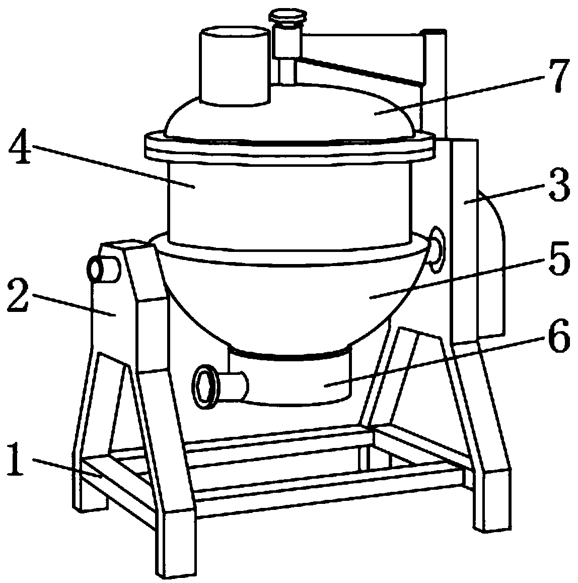
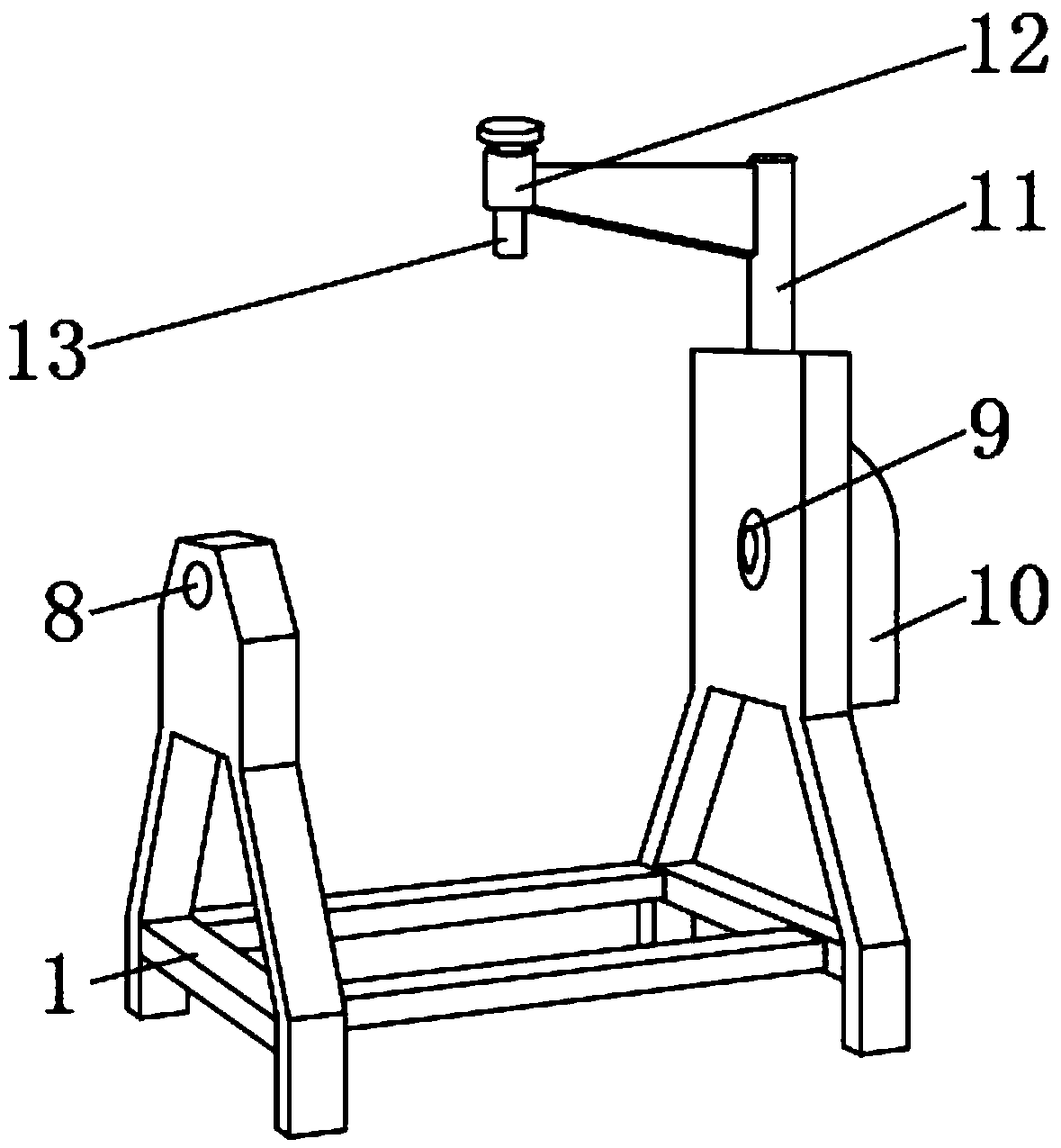
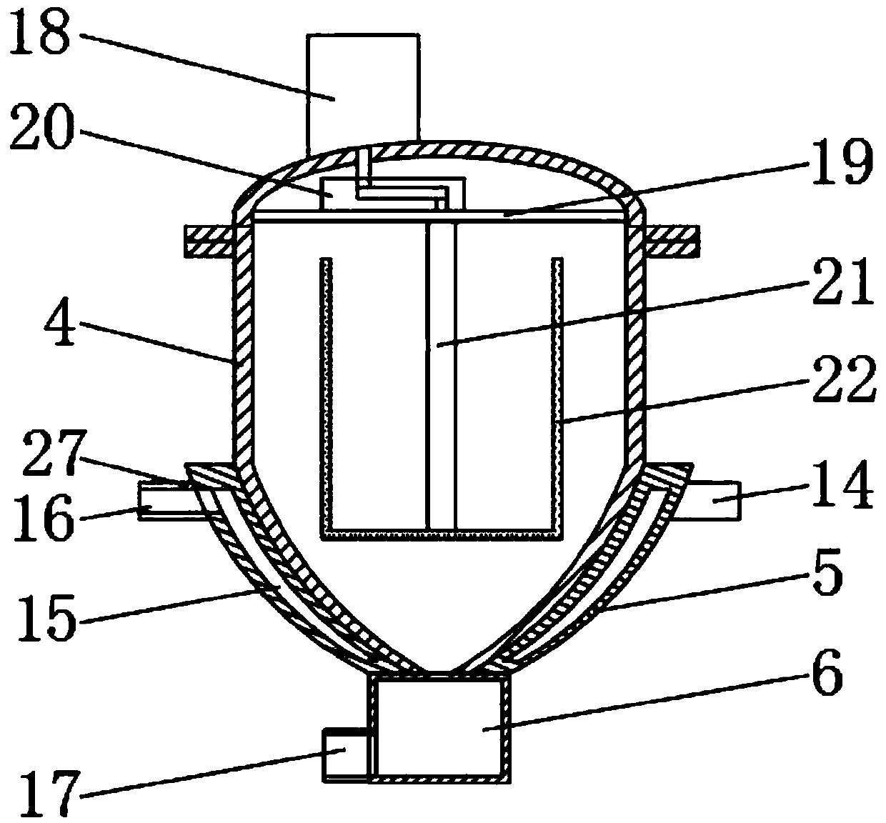
[0026] Such as Figure 1-5 As shown, a soy protein extraction tank device includes a support frame 1 and an extraction tank body 4. The extraction tank body 4 is located at the upper end of the support frame 1, and a support rod 2 is fixedly installed on the upper end side of the support frame 1. The supporting frame 1 is fixedly installed on the other side of the upper end of the No. 2 strut 3, the No. 1 strut 2 is provided with a No. 1 mounting hole 8 inside, and the No. 2 strut 3 is provided with a No. 2 mounting hole 9 inside. A mounting sleeve 5 is fixedly installed on the outer circumferential surface of the bottom end of the mounting sleeve 5. A transmission rod 14 is fixedly installed on the upper side of the mounting sleeve 5, and the transmission rod 14 is located inside the second mounting hole 9, and the upper end of the mounting sleeve 5 is fixed on the other side A driven rod 27 is installed, and the driven rod 27 is located inside the first mounting hole 8.

[002...

Embodiment 2

[0030] Such as Figure 1-5 As shown, a soy protein extraction tank device includes a support frame 1 and an extraction tank body 4. The extraction tank body 4 is located at the upper end of the support frame 1, and a support rod 2 is fixedly installed on the upper end side of the support frame 1. The supporting frame 1 is fixedly installed on the other side of the upper end of the No. 2 strut 3, the No. 1 strut 2 is provided with a No. 1 mounting hole 8 inside, and the No. 2 strut 3 is provided with a No. 2 mounting hole 9 inside. A mounting sleeve 5 is fixedly installed on the outer circumferential surface of the bottom end of the mounting sleeve 5. A transmission rod 14 is fixedly installed on the upper side of the mounting sleeve 5, and the transmission rod 14 is located inside the second mounting hole 9, and the upper end of the mounting sleeve 5 is fixed on the other side A driven rod 27 is installed, and the driven rod 27 is located inside the first mounting hole 8.

[003...

Embodiment 3

[0036] Such as Figure 1-5 As shown, a soy protein extraction tank device includes a support frame 1 and an extraction tank body 4. The extraction tank body 4 is located at the upper end of the support frame 1, and a support rod 2 is fixedly installed on the upper end side of the support frame 1. The supporting frame 1 is fixedly installed on the other side of the upper end of the No. 2 strut 3, the No. 1 strut 2 is provided with a No. 1 mounting hole 8 inside, and the No. 2 strut 3 is provided with a No. 2 mounting hole 9 inside. A mounting sleeve 5 is fixedly installed on the outer circumferential surface of the bottom end of the mounting sleeve 5. A transmission rod 14 is fixedly installed on the upper side of the mounting sleeve 5, and the transmission rod 14 is located inside the second mounting hole 9, and the upper end of the mounting sleeve 5 is fixed on the other side A driven rod 27 is installed, and the driven rod 27 is located inside the first mounting hole 8.

[003...


PUM


Abstract

The invention discloses an extraction tank device for soy proteins. The extraction tank device comprises a support frame and an extraction tank body, wherein the extraction tank body is located at theupper end of the support frame, a support rod I is fixedly mounted on one side of the upper end of the support frame, and a support rod II is fixedly mounted on the other side of the upper end of thesupport frame. According to the extraction tank device for the soy proteins, the extraction tank body can rotate around a transmission rod and a driven rod so as to clean internal filter residue, sothat the detection and maintenance of each part in the extraction tank device are facilitated, and the rotation in different angles can be realized; an upper cover and the extraction tank body can beclosed, a limiting screw hole and an adjusting screw rod can be rotated to one side through the rotation of the rotating rod at the bottom end of the limiting screw hole, so that the loading and the mounting and dismounting of the upper cover are facilitated, the heating or cooling of the extraction tank body is realized, the device can meet different operation demands and is relatively wide in use range; and by arranging an interlayer, a relatively good thermal insulation effect is achieved, and the device has relatively good use prospects.

Description

Technical field [0001] The invention relates to the field of extraction tanks, in particular to a soybean protein extraction tank device. Background technique [0002] Extraction refers to the process of transferring protein solubles in soybeans to a suitable solvent. Common extraction methods include decoction, percolation and dipping. With the improvement of industrial development, extraction tanks are gradually used instead Various complex process methods, the extraction tank has the advantages of energy saving, noise reduction, corrosion resistance, strong production capacity, convenient cleaning, etc. It is widely used in the pharmaceutical industry, food, chemical, beverage and other industrial sectors, as the heating of the ingredients in the extraction material , Necessary equipment for cooling, heat preservation, sterilization treatment or storage of slurry; [0003] The existing soybean protein extraction tank device has certain drawbacks when in use. First of all, the e...

Claims


Application Information

Patent Timeline
Patent Type & Authority Applications(China)
IPC IPC(8): A23J1/14B01D11/02
CPCA23J1/14B01D11/0273
Inventor 王其初王其平梁彥贾虎
Owner 安徽博悦生物科技有限公司
Why Eureka
Try Eureka