body cavity drainage tube

A drainage tube and body cavity technology, which is applied in the field of medical drainage tubes, can solve the problems that anti-adhesion medicine is not easy to spread evenly, hot water cannot ensure sufficient and effective perfusion, and has limited effect.

Active Publication Date: 2021-09-14
孙磊
View PDF8 Cites 0 Cited by
  • Summary
  • Abstract
  • Description
  • Claims
  • Application Information

AI Technical Summary

Problems solved by technology

In addition, all kinds of traditional anti-adhesion medicines are liquid, and the anti-adhesion medicine is not easy to spread evenly in the complex body cavity, and it is easy to flow out of the body together with the exudate in the body cavity along the drainage tube. Therefore, the role of traditional anti-adhesion medicine Limited, unable to effectively prevent the above-mentioned various adhesions
[0003] Body cavity hyperthermic perfusion chemotherapy has gradually emerged in the process of tumor treatment. Body cavity hyperthermic perfusion chemotherapy has been gradually recognized and promoted by the medical field. However, the abdominal drainage tube used for body cavity hyperthermic perfusion is still the traditional tubular drainage tube or spiral multi-channel drainage tube. The above-mentioned traditional drainage tube cannot prevent adhesion and wrapping, and the surrounding of the tube is easy to be wrapped. In the end, during the process of thermal perfusion, hot water cannot ensure sufficient and effective perfusion to most parts of the body cavity, resulting in some tissue omissions during the process of thermal perfusion of the body cavity.

Method used


Image

  • body cavity drainage tube
  • body cavity drainage tube
  • body cavity drainage tube

Examples


Embodiment Construction

[0025] Attached below Figure 1-5 The present invention will be further described with embodiment:

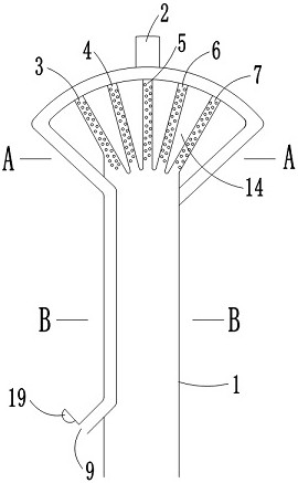
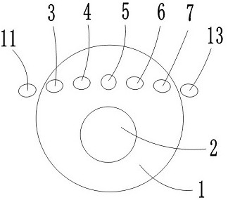
[0026] like figure 1 As shown, a body cavity drainage tube includes a drainage main tube 1, a drainage branch tube A2, a drainage branch tube 3, a drainage branch tube 4, a drainage branch tube 5, a drainage branch tube 6, a drainage branch tube 7 and a support tube 8; One end of the branch pipe A2, the drainage branch pipe 3, the drainage branch pipe 4, the drainage branch pipe 5, the drainage branch pipe 6 and the drainage branch pipe 7 are connected to each other; the drainage branch pipe 2, the drainage branch pipe 3, the drainage branch pipe 4, the drainage branch pipe 5, the drainage branch pipe 6 and the drainage branch pipe 7 The other end of the other end is closed; the side holes 20 are provided on the pipe wall of the drainage branch pipe 2, the drainage branch pipe 3, the drainage branch pipe 4, the drainage branch pipe 5, the drainage branch pipe 6 and the drainag...


PUM


Abstract

The invention discloses a body cavity drainage tube, which comprises a main drainage tube, a drainage branch tube A and N drainage branch tubes B; Closed; one end of the drainage branch pipe B connected to the drainage main pipe is connected to the end surface of one end of the drainage main pipe; one end of the drainage branch pipe A is located in the middle and lower part of the end surface of the drainage main pipe; one end of the drainage branch pipe B is equal to the arc The distance or equidistance is located at the middle and upper part of the end surface of the drainage main pipe; N is a natural number greater than or equal to 2. The body cavity drainage tube claimed in the present invention can replace the traditional tubular drainage tube or spiral multi-channel drainage tube, and is designed as a fan-shaped multi-channel drainage tube, which can not only fully drain the bleeding or exudate in the surgical area, but also reduce the risk of inflammatory adhesions. It can also be used as a body cavity hyperthermic perfusion drainage tube, so that body cavity hyperthermic perfusion chemotherapy can be fully carried out in the body cavity.

Description

technical field [0001] The invention belongs to the field of medical drainage tubes, in particular to a body cavity drainage tube. Background technique [0002] Today, with the increasing number of operations, various complications of surgery have always troubled patients and surgeons. One of the more common ones is adhesions, which form pleural adhesions in the chest cavity, intestinal adhesions in the abdominal cavity, and pelvic adhesions in the pelvic cavity. Traditional tubular or spiral multi-channel drainage tubes are generally placed in the surgical area, at the lowest point around the surgical area. During postoperative recovery, there will be bleeding or inflammatory exudation in and around the surgical wound, which will make the The tissues around the drainage tube adhere to each other and form a package, which prevents the exudate in the body cavity from being fully drained, and the exudate will cause more extensive adhesions at the site. Slight adhesions will c...

Claims


Application Information

Patent Timeline
Patent Type & Authority Patents(China)
IPC IPC(8): A61M25/14
CPCA61M25/0023A61M25/003A61M2025/004
Inventor 孙磊
Owner 孙磊
Why Eureka
Try Eureka