Rotary recliner for vehicle seat

A vehicle seat and rotary technology, which is applied to vehicle seats, vehicle parts, special positions of vehicles, etc., can solve difficult problems such as clutch discs, and achieve the effects of simple structure, slack prevention, and high practicability

Inactive Publication Date: 2019-03-26
重庆韩一汽车座椅有限公司
View PDF8 Cites 1 Cited by
  • Summary
  • Abstract
  • Description
  • Claims
  • Application Information

AI Technical Summary

Problems solved by technology

[0003] However, according to the conventional rotary recliner for a vehicle seat as described above, the bearing 40 is sandwiched in the bearing support hole 11 of the ring gear plate 10, and the center of the hub portion 21 of the large gear plate 20 is opposite to the bearing support hole. 11 is eccentric, due to the shape characteristics of the wedges 71, 72 located therebetween, even if the cam 30 is not rotated, the wedges 71, 72 will appear on the hub due to the external force with the ring gear plate 10 as the medium. 21 is a loose phenomenon of rotation around, and as a result, the ring gear plate 10 and the seatback (seatback) which rotates integrally with it gradually incline toward the rear
[0004] Regarding this point, Korean Registered Patent No. 10-1184190 "Anti-squeezing Recliner (Registration Date: 2012.09.13.)" discloses The clutch discs operating in the meshing state make the ring gear plate 10 non-rotatable and thus solve the technical solution to the above-mentioned slack problem, but in reality it is difficult to realize the above-mentioned clutch discs.
[0005] Also, Korean Registered Patent No. 10-1206803 "Dial Type Recliner (Registration Date: 2012.11.26.)" discloses that the wedge 71, 72 rotation, but it only prevents the further rotation of the wedges 71, 72 that are already rotating, so it cannot prevent the above-mentioned wedges 71, 72 from rotating from the beginning

Method used


Image

  • Rotary recliner for vehicle seat
  • Rotary recliner for vehicle seat
  • Rotary recliner for vehicle seat

Examples


Embodiment Construction

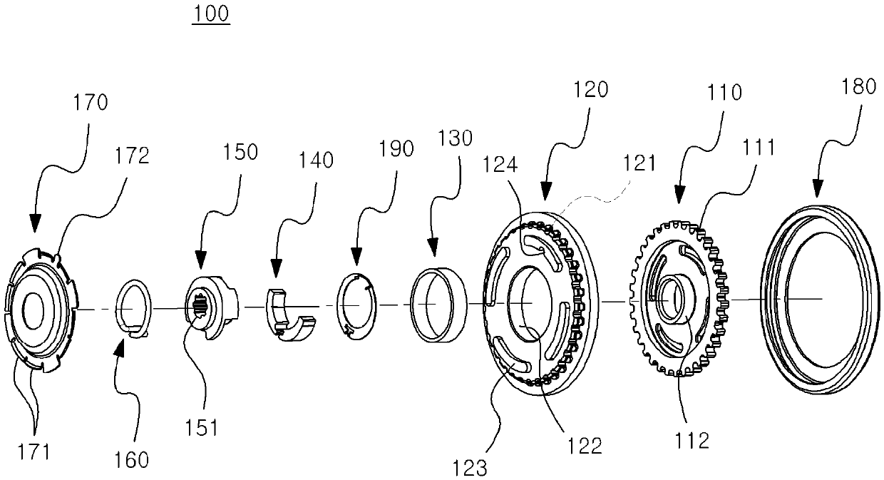
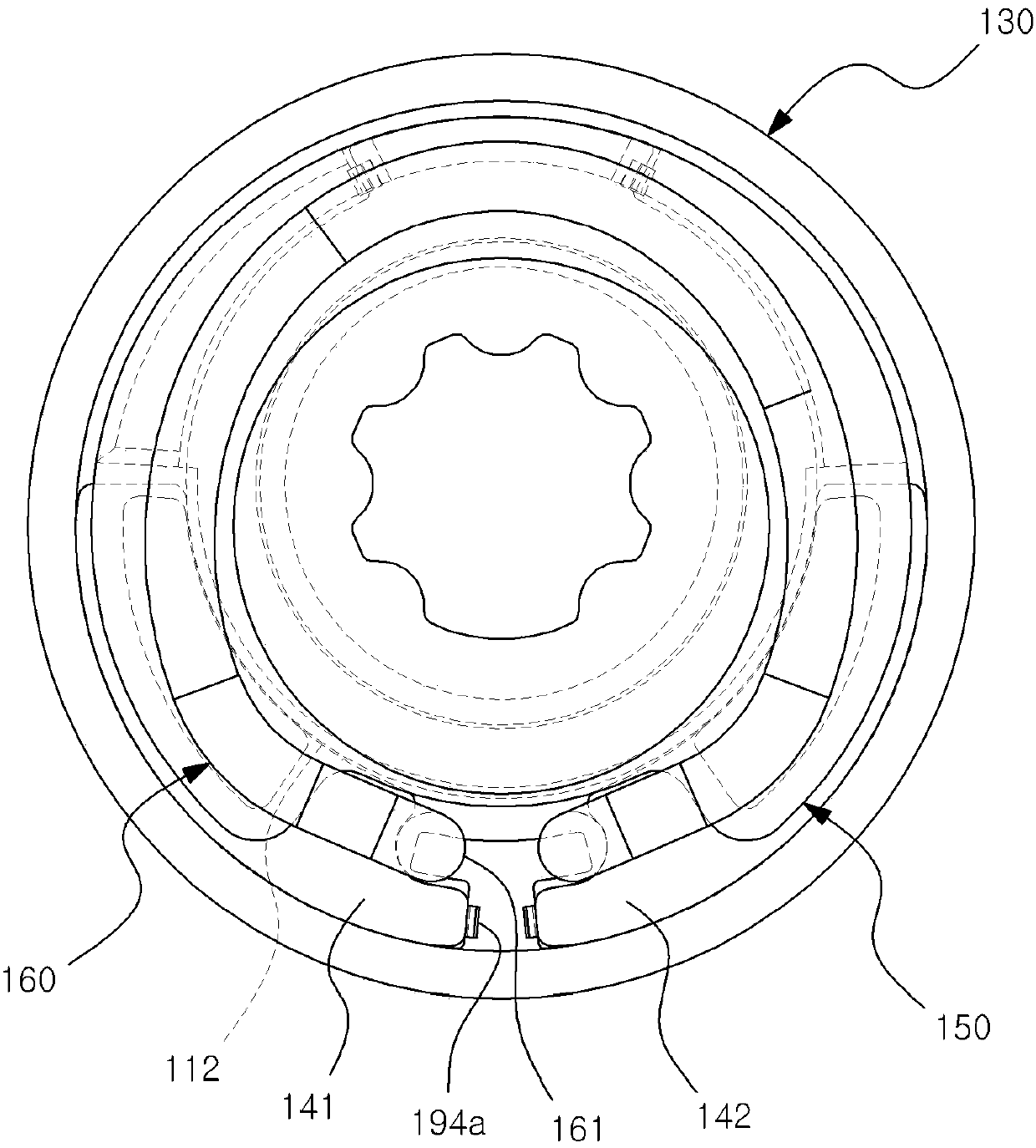
[0030] Such as figure 2 As shown, the structural configuration of the vehicle seat rotary recliner 100 according to the first embodiment of the present invention is as follows, a bearing 130, a pair of wedges 140, a cam 150, and a spring are accommodated between the large gear plate 110 and the ring gear plate 120. 160 and leaf spring 190 are covered and supported by cover plate 170 and outline cover 180 in their state.

[0031] The large gear plate 110 forms outer teeth (outer teeth, 111 ) on the outer peripheral surface and protrudes from the center to form a hub portion (bush, 112 ).

[0032] The ring gear plate 120 has inner teeth (121) for meshing with the outer teeth 111 on the outer peripheral surface, and a circular bearing support hole 122 is formed on the inner side, and the center of the circular bearing support hole 122 is deviated from the hub. Section 112 Center.

[0033] The bearing 130 is sandwiched into the bearing support hole 122 of the ring gear plate 12...


PUM


Abstract

The present invention relates to a rotary recliner for a vehicle seat, which adjusts the reclining angle of a seat back of a vehicle seat according to the rotation pressure based on a handle knob or an electric motor. A rotation adjusting cam extends in the circumferential direction to form a groove part on one side surface which is rotatably combined with a hub part of a bull gear plate in the axial direction. The rotary recliner also comprises a plate spring which is sandwiched in the peripheral edge of the hub part and is in surface contact with one side surface of the cam in the axial direction. The plate spring includes: a pair of stopper protrusions which are inserted into the groove part and are respectively supported by both ends of the groove part in the circumferential directionso as to rotate the plate spring and the cam as a whole; and a pair of locking protrusions that support a pair of wedges, which are rotated and pressurized in the circumferential direction, in contactwith each other in different circumferential directions when the cam performs a rotation operation. Thereby, the plate spring rotating integrally with the cam supports the pair of wedges to prevent the wedges from rotating, i.e., to prevent the wedges from loosening.

Description

technical field [0001] The present invention relates to a recliner for adjusting the reclining angle of the seat back of a vehicle seat, more particularly, a rotary recliner for a vehicle seat by means of a rotary pressure adjustment based on a handle knob or an electric motor reclining angle. Background technique [0002] Such as figure 1 As shown, in general, the rotation pressure of the shaft 1 of the existing vehicle seat rotary recliner belonging to the same technical field as the present invention causes the cam 30 to not only release the locking of the wedges 71, 72 by the spring 90 ( lock) state, and at the same time drive the above-mentioned wedges 71, 72 to rotate along the inner peripheral surface of the bearing 40, thereby realizing the ring gear plate 10 on the internal gear (internal gear) side and the large gear plate 20 on the external gear (external gear) side. relative rotation. [0003] However, according to the conventional rotary recliner for a vehicl...

Claims


Application Information

Patent Timeline
Patent Type & Authority Applications(China)
IPC IPC(8): B60N2/225
CPCB60N2/2213B60N2/225
Inventor 白洪铨朴建永尹基荣
Owner 重庆韩一汽车座椅有限公司
Why Eureka
Try Eureka