A floating body for semi-submerged marine wind power generation equipment

A technology for wind power generation equipment and floating body, which is applied in the field of floating body for semi-submerged marine wind power generation equipment, can solve the problems of reducing fan blade wind energy, increasing cable load, reducing power generation efficiency, etc., and reducing the amplitude of shaking and the amplitude of inclination , to ensure normal operation and increase the effect of power generation efficiency

Active Publication Date: 2020-12-11
杭州煜贤网络科技有限公司
View PDF13 Cites 0 Cited by
  • Summary
  • Abstract
  • Description
  • Claims
  • Application Information

AI Technical Summary

Problems solved by technology

[0003] 1. The floating body equipped with the existing semi-submerged marine wind power generation device does not have the ability of automatic balancing, and the stability is poor. The blades, etc. generate a lateral thrust, causing the semi-submerged marine wind power generation equipment to shake and tilt greatly, the wind energy captured by the fan blades is reduced, and the power generation efficiency is reduced
[0004] 2. When the sway and inclination of the semi-immersed marine wind power generation equipment are too large, the floating body tilts and pulls the corresponding cable strongly, increasing the load on the cable, so that the cable, the connection between the cable and the floating body and the cable The connection with the anchor spindle was broken, causing the semi-submerged offshore wind power equipment to fall and cannot continue to work

Method used


Image

  • A floating body for semi-submerged marine wind power generation equipment
  • A floating body for semi-submerged marine wind power generation equipment
  • A floating body for semi-submerged marine wind power generation equipment

Examples


Embodiment Construction

[0022] The following will clearly and completely describe the technical solutions in the embodiments of the present invention with reference to the accompanying drawings in the embodiments of the present invention. Obviously, the described embodiments are only some, not all, embodiments of the present invention. Based on the embodiments of the present invention, all other embodiments obtained by persons of ordinary skill in the art without making creative efforts belong to the protection scope of the present invention.

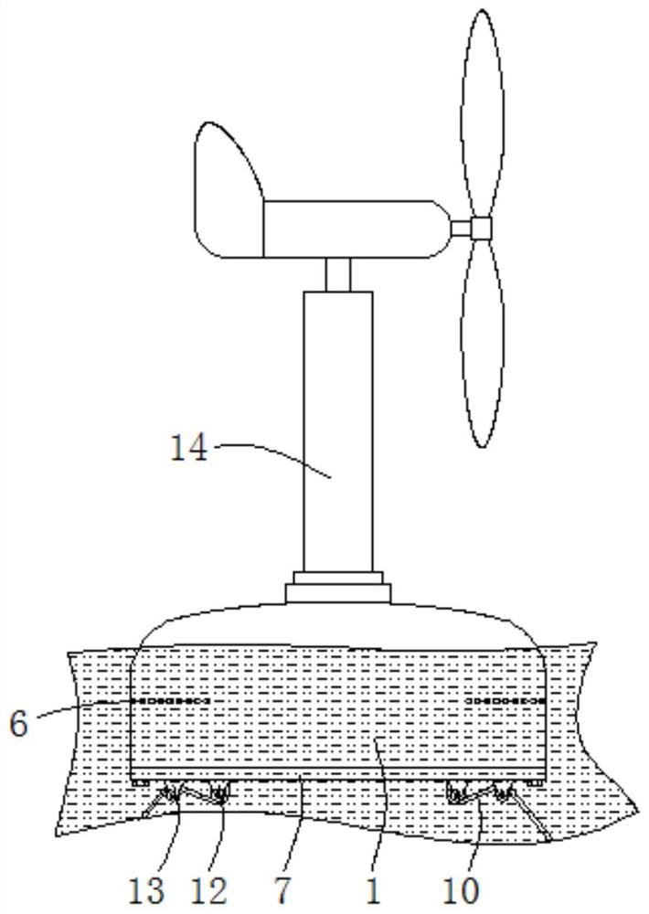
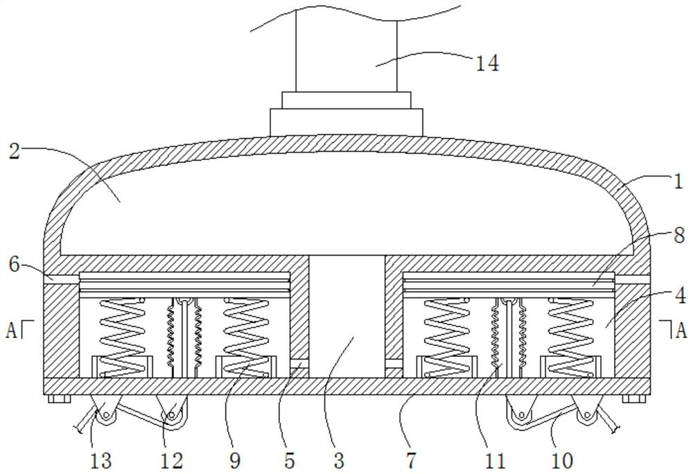
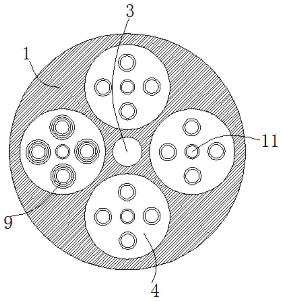
[0023] see Figure 1-3 , a floating body for semi-submerged marine wind power generation equipment, including a floating body 1, a cavity 2 is opened inside the floating body 1, and an air passage 3 located below the cavity 2 is opened inside the floating body 1 , the top of the air passage 3 communicates with the cavity 2, the inside of the floating body 1 is provided with a buffer chamber 4 around the air passage 3, the number of the buffer chambers 4 is fou...


PUM


Abstract

The invention relates to the technical field of ocean wind power generation equipment and discloses a floating body for semi-submerged ocean wind power generation equipment. The floating body for thesemi-submerged ocean wind power generation equipment comprises a floating body; a cavity is formed in the floating body; an air passage under the cavity is formed in the floating body; and the top ofthe air passage communicates with the cavity. The other side of the floating body is upturned and pulls a corresponding cable; the cable pulls a corresponding piston to move downwards so that a waterinlet communicates with a buffering cavity; seawater is sucked into the buffering cavity through the water inlet so that the gravity force of the upturned side of the floating body is increased, the inclination resistance of the floating body is increased and the inclination amplitude of the floating body is reduced; and therefore, the floating body recovers to a horizontal state under an effect of a gravity force so as to realize a purpose of automatic balancing of the floating body; and the shaking amplitude and inclination amplitude of a wind power generation component are reduced, the stability of an ocean wind power generation device is enhanced, the normal working of the ocean wind power generation device is guaranteed, and the power generation efficiency is enhanced.

Description

technical field [0001] The invention relates to the technical field of marine wind power generation equipment, in particular to a floating body for semi-submerged marine wind power generation equipment. Background technique [0002] Ocean wind power generation equipment refers to equipment that can convert wind energy on the ocean into electrical energy. According to different support forms, it can be divided into two types: bottom fixed type and floating type. Among them, the semi-submerged marine wind power generation equipment is mainly composed of anchors, cables, floating bodies, connecting rods, generators and fan blades. The floating bodies are immersed in water and connected to the anchors on the seabed through cables. The interference is small, and it can support large wind turbines with a rotor diameter of 3-6MW and a rotor diameter of 80m. It is widely used in wind farms in remote sea areas. The floating body equipped with the existing semi-immersed marine wind po...

Claims


Application Information

Patent Timeline
Patent Type & Authority Patents(China)
IPC IPC(8): B63B35/44F03D13/25
CPCB63B35/44B63B2035/446F03D13/25Y02E10/72Y02E10/727
Inventor 不公告发明人
Owner 杭州煜贤网络科技有限公司
Why Eureka
Try Eureka