
Pneumatic electromagnetic catapult

A catapult and electromagnetic technology, which is applied in the direction of launching/dragging transmission devices, can solve the problems of small ejection force, long installation and maintenance cycle, and insufficient power, and achieve small ejection area, energy saving, strong practicability, and work efficiency high effect

Pending Publication Date: 2019-03-26
刘铭 +1
View PDF0 Cites 1 Cited by
  • Summary
  • Abstract
  • Description
  • Claims
  • Application Information

AI Technical Summary

Problems solved by technology

The use of steam on an aircraft carrier has a large ejection space, insufficient steam, and small ejection force. Installation and maintenance are restricted. The electronic pulse electromagnetic catapult uses nuclear power. It needs to be buffered for more than 40 seconds for a launch, and it can be launched again when it is charged to more than 300 megajoules. It reflects the lack of power, the need for a large area of ​​space, and the long installation and maintenance cycle. Only two sets can be installed on the aircraft carrier. The disadvantages of the current electronic pulse electromagnetic catapult are: the required runway is long and the load capacity is small. long takeoff time

Method used


Image

  • Pneumatic electromagnetic catapult
  • Pneumatic electromagnetic catapult
  • Pneumatic electromagnetic catapult

Examples


Embodiment Construction

[0038] The present invention will be described in further detail below in conjunction with the accompanying drawings.

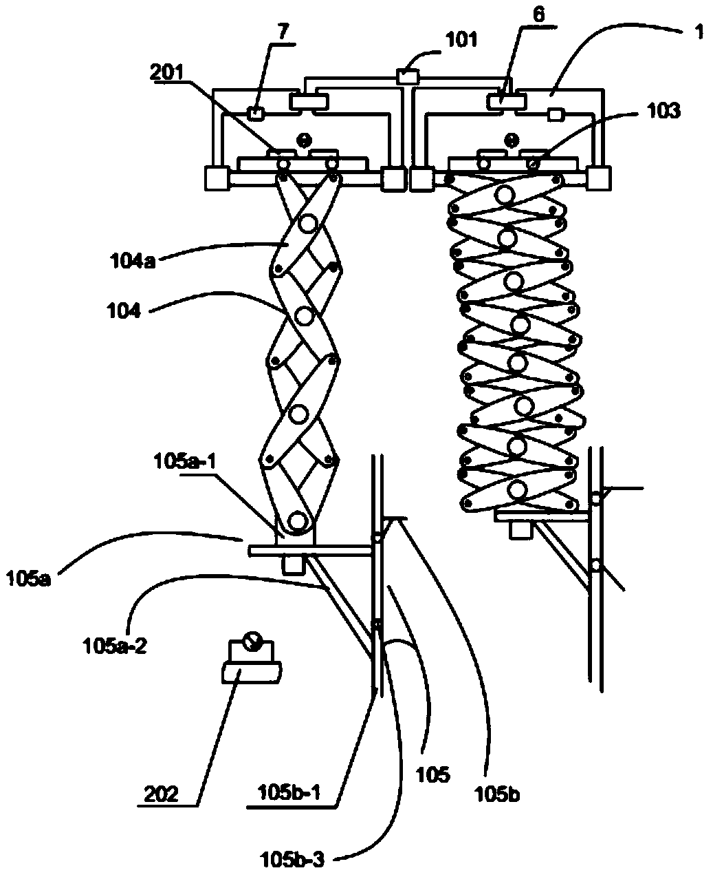
[0039] combined with Figure 1-12 , an aero-electromagnetic catapult comprising even pairs of interconnected pneumatic groups 1 and electromagnetic groups 2, wherein,

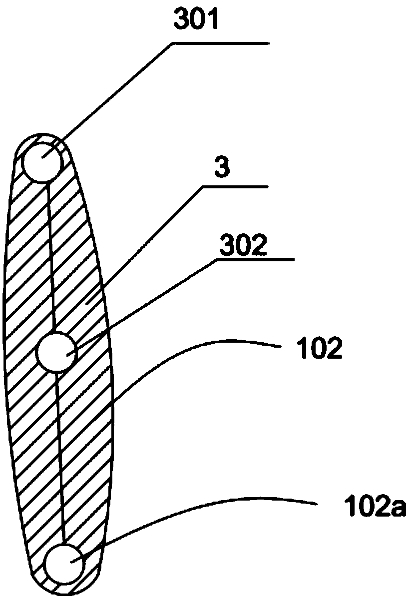
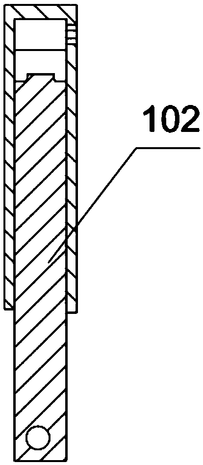
[0040] The pneumatic group 1 includes a high-pressure air source 101, an air source pushing part 102, a connection assembly 103, a telescoping part 104 and an ejection part 105. The high-pressure air source 101 delivers the air source to the air source pushing part 102 to make it unfold, and the expanded air source pushes The part 102 drives the connecting assembly 103 to move, so that the magnetic circuit of the electromagnetic group 2 is connected; the expanded air source pushing part 102 drives the telescopic part 104 to expand or contract, and then drives the ejection part 105 to move when the telescopic part 104 is stretched, and Eject the ejection target;

[0041] The electromagnetic g...


PUM


Abstract

The invention relates to a pneumatic electromagnetic catapult. The pneumatic electromagnetic catapult comprises an even number of connected pneumatic groups and electromagnetic groups, wherein the pneumatic groups comprise high pressure gas sources, gas source pushing parts, connecting components, telescopic parts and catapulting parts; the high pressure gas sources convey gas sources to the gas source pushing parts so that the gas source pushing parts are unfolded; the electromagnetic groups comprise permanent magnets and electromagnetic coils; when the gas source pushing parts are unfolded,the electromagnetic coils are connected and opposite poles of the electromagnetic coils and the permanent magnets attract each other; and when the gas source pushing parts retract, circuits of the electromagnetic coils are reversely connected and like poles of the electromagnetic coils and the permanent magnets repel each other. According to the pneumatic electromagnetic catapult, as the multiplepneumatic groups and the multiple electromagnetic groups are arranged, and multiple catapulting slide ways are arranged, a purpose of simultaneously ejecting multiple airplanes is realized, the working efficiency is high, and the catapulting floor space is small; as the high pressure gas sources and the electromagnetic groups are arranged, the pushing interaction force is larger so that a catapulting purpose is realized on the basis of saving other primary energies, the energy-saving performance and the practicability are both higher, and the pneumatic electromagnetic catapult can be widely applied to the technical field of underwater equipment.

Description

technical field [0001] The invention relates to the technical field of underwater equipment, in particular to a pneumatic electromagnetic catapult. Background technique [0002] At present, with the increasing economic level and scientific and technological strength of our country, the research and development of underwater aircraft carriers has gradually deepened, providing a strong guarantee for the development of our country's military and other fields. The use of steam on an aircraft carrier has a large ejection space, insufficient steam, and small ejection force. Installation and maintenance are restricted. The electronic pulse electromagnetic catapult uses nuclear power. It needs to be buffered for more than 40 seconds for a launch, and it can be launched again when it is charged to more than 300 megajoules. It reflects the lack of power, the need for a large area of ​​space, and the long installation and maintenance cycle. Only two sets can be installed on the aircraf...

Claims


Application Information

Patent Timeline
Patent Type & Authority Applications(China)
IPC IPC(8): B64F1/06
CPCB64F1/06
Inventor 刘铭刘振峰
Owner 刘铭
Learn More