Gluing head control mechanism of full automatic gluing flanging machine

A technology of a control mechanism and a folding machine, which is applied to the field of gluing mechanism of leather products, can solve the problems of overflowing glue, unstable glue control of automatic folding machine, and inability to lift the glue head, so as to avoid trimming and removing glue. work, avoid unstable operation, and overcome the effect of work fatigue

Inactive Publication Date: 2019-03-26
ANHUI JINTAI METAL MOLD STRUCTURE
View PDF0 Cites 0 Cited by
  • Summary
  • Abstract
  • Description
  • Claims
  • Application Information

AI Technical Summary

Problems solved by technology

[0002] The automatic gluing and folding machine is suitable for PVC, PU, ​​natural leather, artificial leather, cloth and other materials of leather products such as shoes, purses, wallets, and mobile phone cases. It uses hot-melt adhesive for folding operations, which is common in the prior art. The glue head of the edge folding machine cannot be lifted. If you want to lift the glue head, you often need to lift the workbench or adjust the inclination angle of the workbench, resulting in inaccurate control of the return position of the glue head, resulting in inaccurate control of the glue output of the automatic edge folding machine. Problems such as stability and glue overflow occur. The present invention provides a rubber head lifting mechanism of an automatic gluing and folding machine. The glue head control mechanism of the automatic gluing and folding machine has a simple and compact structure, accurate position control, stable and reliable operation No glue leakage, suitable for popularization

Method used


Image

  • Gluing head control mechanism of full automatic gluing flanging machine
  • Gluing head control mechanism of full automatic gluing flanging machine
  • Gluing head control mechanism of full automatic gluing flanging machine

Examples


Embodiment Construction

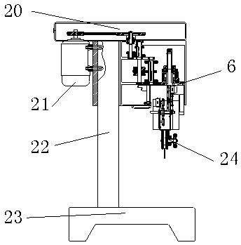
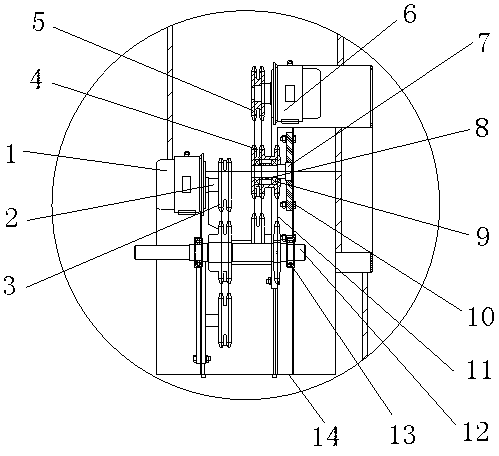
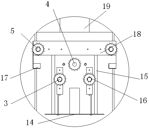
[0018] Below in conjunction with accompanying drawing and embodiment of description, specific embodiment of the present invention is described in further detail:

[0019] see Figure 1-4 , the present invention provides a technical solution: a rubber head control mechanism of a fully automatic gluing and folding machine, including a first motor 1, the first motor 1 is a stepping motor that converts electrical pulse signals into angular displacement or The electromechanical components of linear displacement, the input of the stepping motor is a pulse sequence, and the output is the corresponding incremental displacement or stepping motion. Under normal motion, it has a fixed number of steps per revolution and performs continuous stepping motion. , its rotation speed and the frequency of the input pulse maintain a strict corresponding relationship, and it is not affected by voltage fluctuations and load changes. Since the stepping motor can directly accept digital control, it is...


PUM


Abstract

The invention discloses a gluing head control mechanism of a full automatic gluing flanging machine. The gluing head control mechanism comprises a first motor. A first rotating shaft is mounted on theright side of the first motor. A first belt wheel is connected to the outer wall of the first rotating shaft in a sleeving mode. A first belt is arranged on the right side of the first belt wheel. Asecond belt wheel is connected to the inner wall of the first belt in a sleeving mode. A second motor is connected to the right side of the second belt wheel. A second rotating shaft is arranged belowthe second motor. A first bearing is arranged on the left side of a shaft sleeve. According to the gluing head control mechanism of the full automatic gluing flanging machine, through cooperation ofthe first rotating shaft, the first belt wheel, the first belt, the first rotating shaft and the second rotating shaft, gluing head sealing of the full automatic gluing flanging machine is more firm,glue overflow is avoided, glue marks and prints are produced on an operated surface, and therefore the condition that a product needs secondary edge refining and glue removing operation by operator isavoided, and the production cost of enterprises is saved.

Description

technical field [0001] The invention relates to the technical field of gluing mechanisms for leather products, in particular to a glue head control mechanism of a fully automatic gluing and folding machine. Background technique [0002] The automatic gluing and folding machine is suitable for PVC, PU, ​​natural leather, artificial leather, cloth and other materials of leather products such as shoes, purses, wallets, and mobile phone cases. It uses hot-melt adhesive for folding operations, which is common in the prior art. The glue head of the edge folding machine cannot be lifted. If you want to lift the glue head, you often need to lift the workbench or adjust the inclination angle of the workbench, resulting in inaccurate control of the return position of the glue head, resulting in inaccurate control of the glue output of the automatic edge folding machine. Problems such as stability and glue overflow occur. The present invention provides a rubber head lifting mechanism o...

Claims


Application Information

Patent Timeline
Patent Type & Authority Applications(China)
IPC IPC(8): B65H45/30
CPCB65H45/30B65H2701/178
Inventor 王瑞
Owner ANHUI JINTAI METAL MOLD STRUCTURE
Why Eureka
Try Eureka