Hydropower house tail water channel bottom slope structure facilitating fish migration

A technology for powerhouses and tailraces of hydropower stations, applied in water conservancy engineering, marine engineering, climate change adaptation, etc., can solve problems such as unfavorable fish upwards, difficulty in selecting the location of fishway entrances, and complex hydraulic conditions.

Pending Publication Date: 2019-03-26
POWERCHINA BEIJING ENG
View PDF0 Cites 2 Cited by
  • Summary
  • Abstract
  • Description
  • Claims
  • Application Information

AI Technical Summary

Problems solved by technology

[0003] The operation of the power station is based on the dispatching of the power grid, and there are various power generation operating conditions. There are often situations such as one generator generating electricity and multiple generators generating electricity. Stable, not conducive to the upward movement of fish
The bottom slope of the tailrace channel of the powerhouse of the hydropower station is generally a one-way slope. Part of the water flow in the tailrace channel of the powerhouse returns to the upstream, and part of it diffuses downstream. The hydraulic conditions are complex, the flow field is disordered, the location of the fishway inlet is difficult to choose, and the fish passing effect is not ideal.

Method used


Image

  • Hydropower house tail water channel bottom slope structure facilitating fish migration
  • Hydropower house tail water channel bottom slope structure facilitating fish migration
  • Hydropower house tail water channel bottom slope structure facilitating fish migration

Examples


Embodiment Construction

[0012] Below in conjunction with accompanying drawing and specific embodiment the present invention is described in further detail:

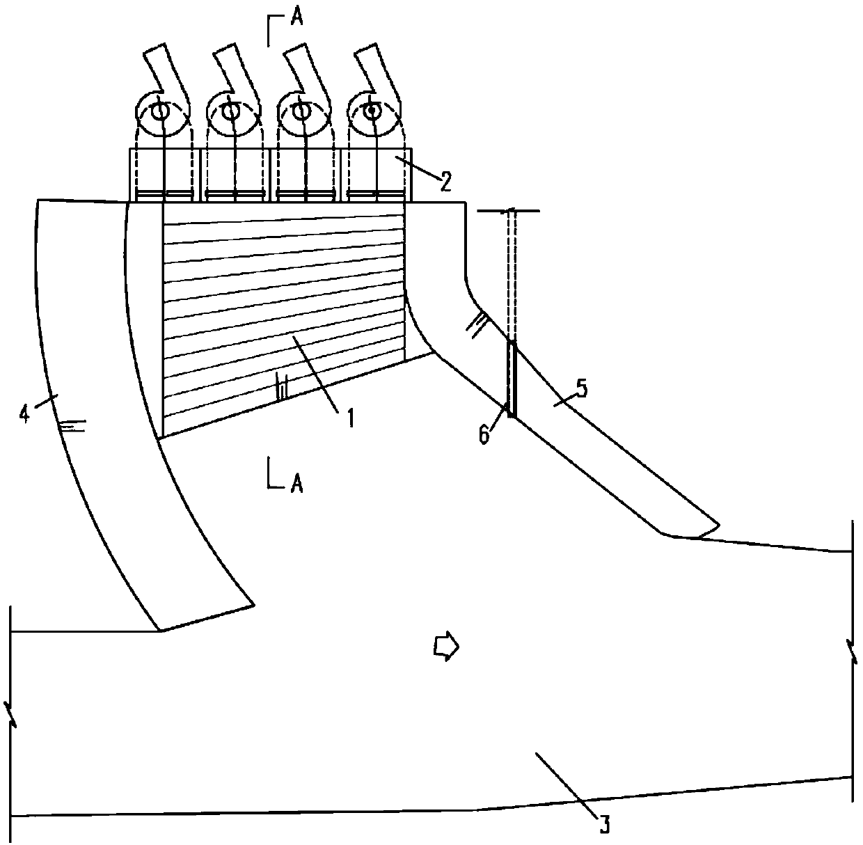
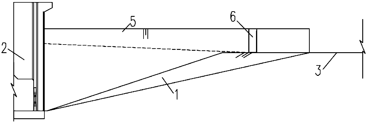
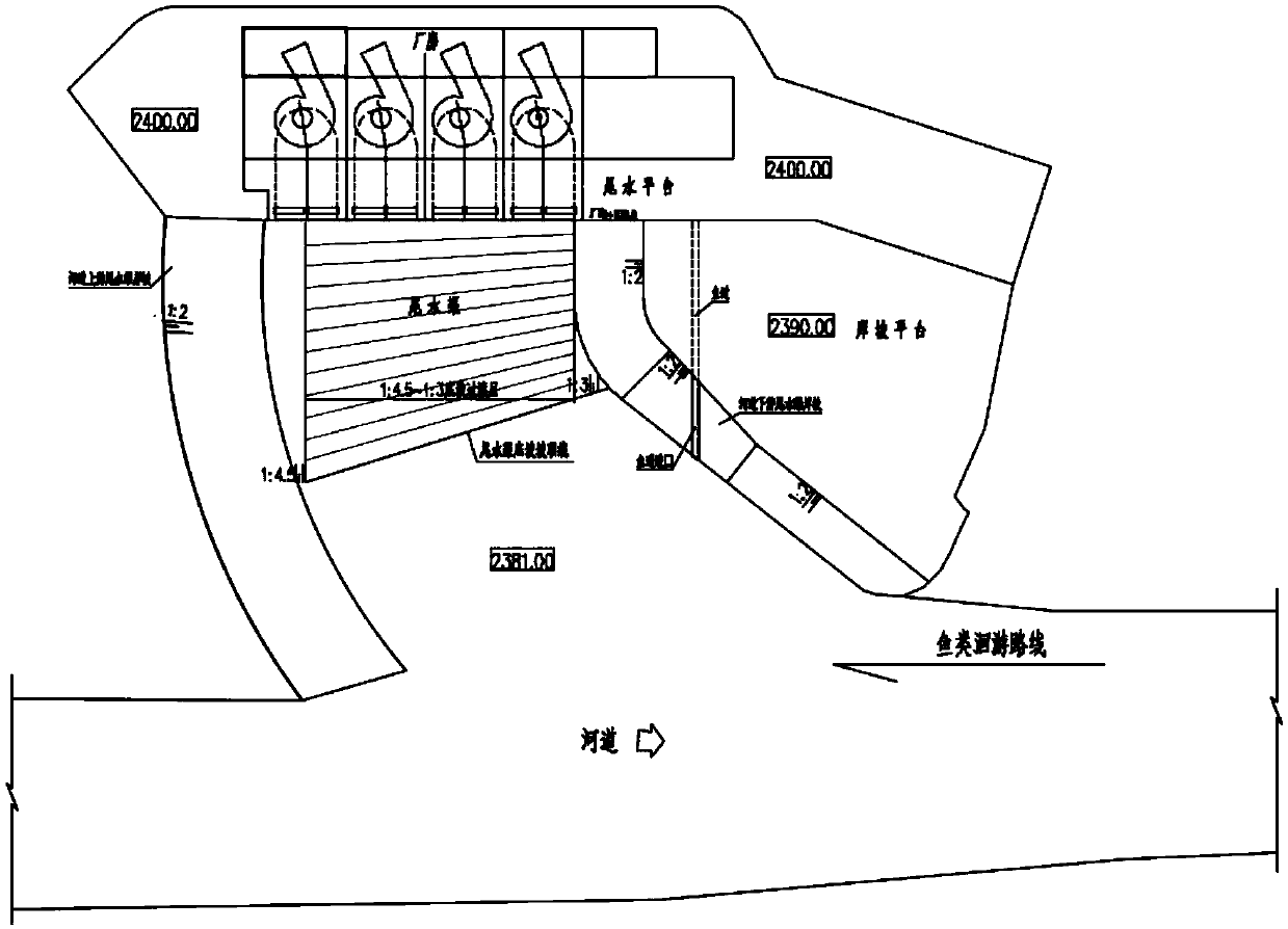
[0013] Such as Figure 1-2 As shown, the tailrace bottom slope structure of the powerhouse of the hydropower station that is conducive to fish migration in the present invention, the tailrace bottom slope 1 adopts the gradual bottom slope inclined to the powerhouse 2, and the tailrace bottom slope 1 slope is from the upstream tailrace bank slope 4 to the downstream of the river The tailrace bank slope 5 gradually increases, and the tailrace bank slope 5 in the downstream of the river channel forms a flow field condition suitable for fish gathering.

[0014] Preferably, the tailrace bottom slope 1 has a slope of 1:4.5 at the position near the tailrace bank slope 4 upstream of the river channel, and the slope at the position near the tailrace channel bank slope 5 downstream of the river channel is 1:3, and the middle part of the tailrace bottom sl...


PUM


Abstract

The invention discloses a hydropower house tail water channel bottom slope structure facilitating fish migration. A tail water channel bottom slope adopts a gradual change bottom slope inclined to a plant, the slope degrees of the tail water channel bottom slope are gradually increased from the riverway upstream tail water channel bank slope to the riverway downstream tail water channel bank slope, and the riverway downstream tail water channel bank slope forms a flow field condition suitable for fish gathering. The slope degree of the portion, close to the riverway upstream tail water channelbank slope, of the tail water channel bottom slope is 1:4.5, the slope degree of the portion, close to the riverway downstream tail water channel bank slope, of the tail water channel bottom slope is1:3, and the middle part of the tail water channel bottom slope is gradually increased from 1:4.5 to 1:3. By means of the hydropower house tail water channel bottom slope structure, the bottom slopeinclined to a tail water channel is changed into the gradual change bottom slope inclined to the plant, a water flow path in the tail water channel of the plant is limited, main flow is inclined to the upstream side of the river channel, meanwhile, the riverway downstream side tail water channel bottom slope is locally lifted to then increase the flow speed of the water flow at the position, the flow field conditions in the tail water channel are improved, accumulation of fish in the riverway downstream side tail water channel bottom slope is facilitated, a fishway inlet is formed in the corresponding position, and the fish passing effect can be effectively improved.

Description

technical field [0001] The invention relates to a water flow control structure of a water conservancy and hydropower project, in particular to a bottom slope structure of a tailrace canal of a powerhouse of a hydropower station which is conducive to fish migration. Background technique [0002] At present, most hydropower projects have been equipped with fish facilities. Fishways are a relatively common way. The entrances of fishways are generally arranged on both sides of the river. Fish congregate. The water velocity near the outlet of the tailrace channel of the power station is higher than that of the river channel, which is conducive to attracting fish upstream and is a commonly used location. [0003] The operation of the power station is based on the dispatching of the power grid, and there are various power generation operating conditions. There are often situations such as one generator generating electricity and multiple generators generating electricity. Stable,...

Claims


Application Information

Patent Timeline
Patent Type & Authority Applications(China)
IPC IPC(8): E02B8/08
CPCE02B8/085Y02A40/60
Inventor 邓毅国陈晴龙文李向阳孙双科李广宁
Owner POWERCHINA BEIJING ENG
Why Eureka
Try Eureka