Hydraulic jet energy-saving anti-blocking device

A technology of hydraulic jet and anti-blocking device, which is applied in the direction of cleaning equipment, isolation devices, wellbore/well parts, etc., can solve the problems of ineffectiveness, single viscosity reduction principle, and low efficiency of sonic wax removal technology, so as to increase production , good separation effect

Pending Publication Date: 2019-03-26
冯鹏
View PDF0 Cites 2 Cited by
  • Summary
  • Abstract
  • Description
  • Claims
  • Application Information

AI Technical Summary

Problems solved by technology

The current sonic wax anti-viscosity reduction technology still has low efficiency of sonic wax removal technology, and many of them do...

Method used


Image

  • Hydraulic jet energy-saving anti-blocking device
  • Hydraulic jet energy-saving anti-blocking device
  • Hydraulic jet energy-saving anti-blocking device

Examples


Embodiment 1

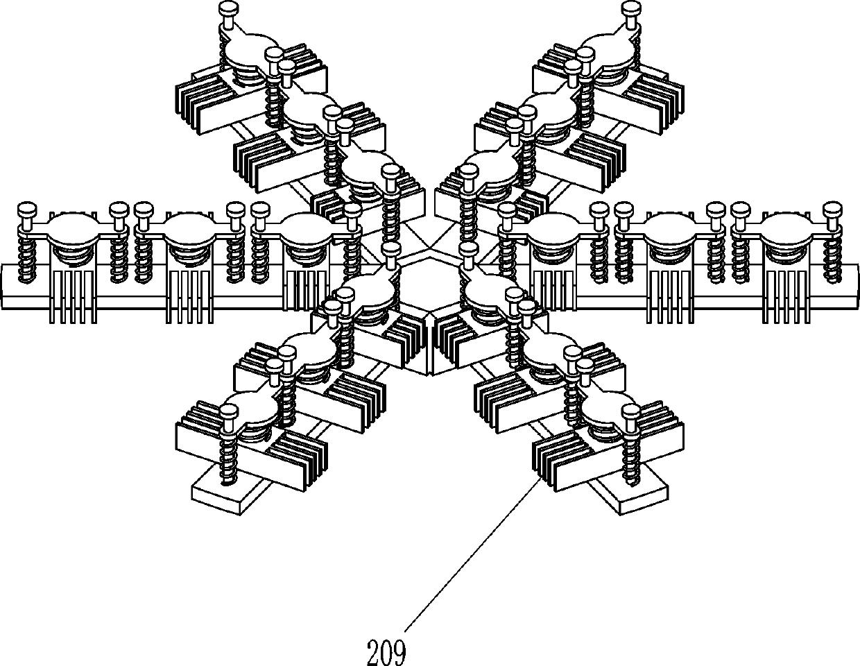
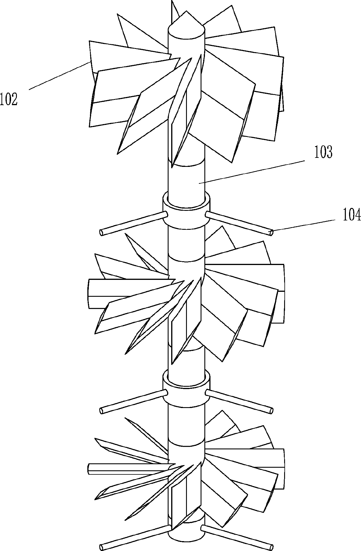
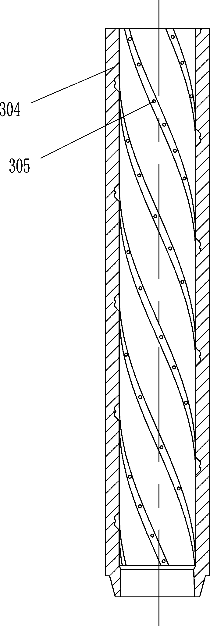
[0029] A hydrojet energy-saving anti-blocking device, such as Figure 1-9As shown, it includes a multi-stage rotary cutting particle refiner 1, a self-heating separator 2, a swirl generator 3 and a multi-stage ultrasonic oscillator 4. The lower side of the multi-stage rotary cutting particle refiner 1 is detachably connected with Self-heating separator 2, the swirl generator 3 is detachably connected to the lower side of the self-heating separator 2, and the swirl generator 3 includes an inner swirl fixed frame 301, a multi-stage inner swirl 302, an arc-shaped inner swirl The flow fixing seat 303, the outer swirl sleeve 304 and the circular convex ball 305, the lower side of the self-heating separator 2 and the upper side of the outer swirl sleeve 304 are detachably connected, and the inner wall of the outer swirl sleeve 304 is processed with an arc Guide groove, the inner wall of the arc-shaped guide groove is discretely distributed with circular convex balls 305, the inner s...

Embodiment 2

[0031] A hydrojet energy-saving anti-blocking device, such as Figure 1-9 As shown, it includes a multi-stage rotary cutting particle refiner 1, a self-heating separator 2, a swirl generator 3 and a multi-stage ultrasonic oscillator 4. The lower side of the multi-stage rotary cutting particle refiner 1 is detachably connected with Self-heating separator 2, the swirl generator 3 is detachably connected to the lower side of the self-heating separator 2, and the swirl generator 3 includes an inner swirl fixed frame 301, a multi-stage inner swirl 302, an arc-shaped inner swirl The flow fixing seat 303, the outer swirl sleeve 304 and the circular convex ball 305, the lower side of the self-heating separator 2 and the upper side of the outer swirl sleeve 304 are detachably connected, and the inner wall of the outer swirl sleeve 304 is processed with an arc Guide groove, the inner wall of the arc-shaped guide groove is discretely distributed with circular convex balls 305, the inner ...

Embodiment 3

[0034] A hydrojet energy-saving anti-blocking device, such as Figure 1-9 As shown, it includes a multi-stage rotary cutting particle refiner 1, a self-heating separator 2, a swirl generator 3 and a multi-stage ultrasonic oscillator 4. The lower side of the multi-stage rotary cutting particle refiner 1 is detachably connected with Self-heating separator 2, the swirl generator 3 is detachably connected to the lower side of the self-heating separator 2, and the swirl generator 3 includes an inner swirl fixed frame 301, a multi-stage inner swirl 302, an arc-shaped inner swirl The flow fixing seat 303, the outer swirl sleeve 304 and the circular convex ball 305, the lower side of the self-heating separator 2 and the upper side of the outer swirl sleeve 304 are detachably connected, and the inner wall of the outer swirl sleeve 304 is processed with an arc Guide groove, the inner wall of the arc-shaped guide groove is discretely distributed with circular convex balls 305, the inner ...


PUM


Abstract

The invention relates to an anti-blocking device, in particular to a hydraulic jet energy-saving anti-blocking device. The technical problem to be solved is how to provide a hydraulic jet energy-saving anti-blocking device which effectively reduces viscosity, allows normal flow of oil, and increases production. The technical scheme is that the hydraulic jet energy-saving anti-blocking device includes a multi-stage rotary cutting particle refiner and the like. The lower side of the multi-stage rotary cutting particle refiner is detachably connected with a self-heating separator, the lower sideof the self-heating separator is detachably connected with a swirling flow generator, the swirling flow generator includes an inner rotational flow fixing frame, a multi-stage inner swirler, an arc-shaped inner swirling flow fixing seat, an outer swirling flow sleeve and a circular convex ball. Solid particles in fluid are cut and refined through the multi-stage rotary cutting particle refiner, the self-heating separator heats the fluid by converting mechanical energy of the fluid into thermal energy through the friction effect, and the swirling flow generator can better separate the particlesin the liquid under the swirling flow action.

Description

technical field [0001] The invention relates to an anti-blocking device, in particular to a hydraulic jet energy-saving anti-blocking device. Background technique [0002] Crude oil is a multi-phase hydrocarbon mixture. When the temperature of waxy crude oil is lower than the precipitation temperature of paraffin crystals, a large amount of paraffin is precipitated, and the viscosity of crude oil increases rapidly; when the viscosity of crude oil is high, the temperature is lower than the precipitation temperature. At this time, a large amount of colloidal bitumen will be precipitated, and the viscosity of crude oil will increase rapidly. When the number of paraffin crystals increases, a cross-linked network structure will be formed, and the strength will continue to increase, which will eventually lead to the loss of fluidity of crude oil, seriously affecting the normal production and transportation of crude oil, and for pumping wells, it will cause increased load, pump jam...

Claims


Application Information

Patent Timeline
IPC IPC(8): E21B37/02E21B36/00E21B28/00
CPCE21B28/00E21B36/00E21B37/02
Inventor 冯鹏樊林栋王凤刚
Owner 冯鹏
Why Eureka
Try Eureka