A centripetal turbine device with vibration damping and sealing structure

A technology of turbine device and sealing structure, which is applied to the supporting elements of blades, machines/engines, mechanical equipment, etc., can solve the problems of aerodynamic efficiency, impeller life and safe operation of centripetal turbines, affecting the aerodynamic efficiency of turbines, and easy operation. Problems such as wear and tear occur, and the effect of improving rigidity, improving leakage and improving impeller rigidity can be achieved.

Active Publication Date: 2020-03-17
XI AN JIAOTONG UNIV
View PDF4 Cites 1 Cited by
  • Summary
  • Abstract
  • Description
  • Claims
  • Application Information

AI Technical Summary

Problems solved by technology

The closed impeller cover is attached to the blade, which has a large mass and large centrifugal force, and has the disadvantages of being difficult to clean. It is difficult to work in the fluid working medium with impurities. In the semi-open impeller, the impeller between the cover and the blade The head clearance will greatly affect the aerodynamic efficiency of the turbine
In order to improve efficiency, it is necessary to reduce the blade tip clearance as much as possible. Therefore, the blade flutter of the turbine impeller during operation causes the blade tip of the impeller inlet and outlet to be easily worn, which affects the aerodynamic efficiency, impeller life and safety of the centripetal turbine. Extremely unfavorable

Method used


Image

  • A centripetal turbine device with vibration damping and sealing structure
  • A centripetal turbine device with vibration damping and sealing structure
  • A centripetal turbine device with vibration damping and sealing structure

Examples


Embodiment Construction

[0022] The present invention will be further described below in conjunction with accompanying drawing.

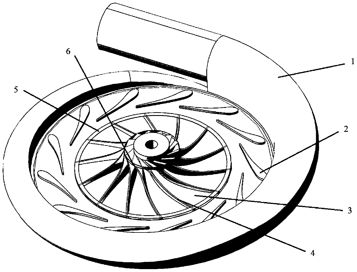
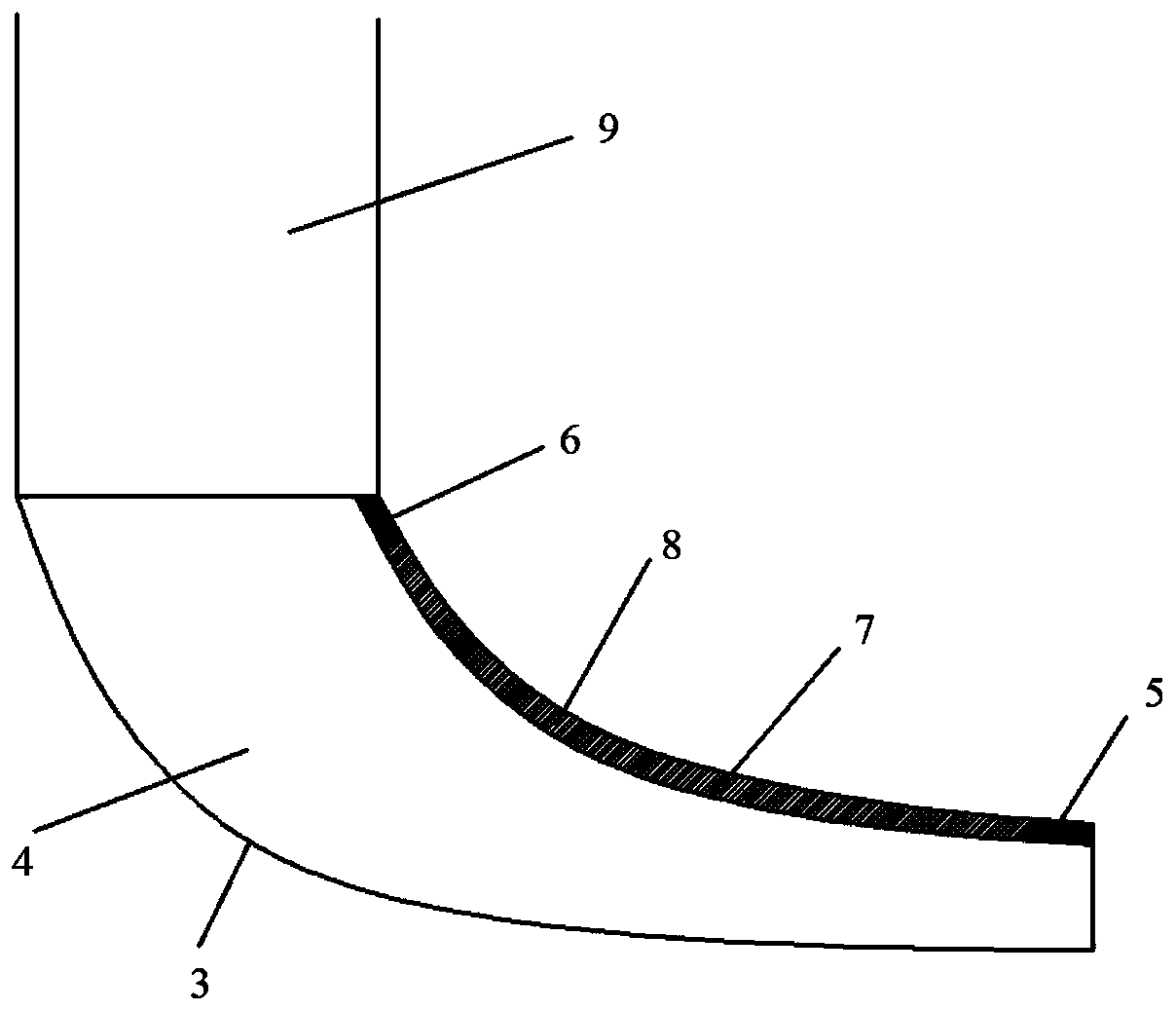
[0023] refer to figure 1 and figure 2 , a centripetal turbine device with a vibration damping and sealing structure provided by the present invention includes a volute 1, a hub 3 and a wheel cover 7 arranged at the center of the volute 1, and several nozzles arranged in the circumferential direction of the hub 3 The centripetal turbine impeller blade 4 at the ring 2 and the center, and the outlet channel 9 connected to the outlet of the centripetal turbine impeller blade 4; Belt 5 and blade outlet shroud 6, and in the impeller flow channel, brush seal 8 is used between the wheel cover 7 and the centripetal turbine blade 4; wherein, the hub 3 and the centripetal turbine blade 4 form the impeller together. The working medium first enters the centripetal turbine device from the volute 1, and then enters the nozzle ring 2, where the pressure of the high-temperature and high-...


PUM


Abstract

The invention provides a radial-inward-flow turbine device with a shock-absorbing damping function and a sealing structure. During work, a working medium enters the radial-inward-flow turbine device through an air inlet volute firstly, and then enters nozzle rings, the pressure of the high-temperature and high-pressure working medium is gradually decreased, the flowing speed is gradually increased, the working medium at outlets of the nozzle rings enters from an inlet of an impeller and does work through expansion in the impeller, and the pressure and the temperature are gradually decreased; and in the impeller, the working medium is subjected to flow guiding by closed flow channels formed by blade inlet shrouds and a hub firstly, then arrives at the middles of impeller blades of a radial-inward-flow turbine to continue doing work through expansion, and finally passes through closed flow channels formed by blade outlet shrouds and the hub, and the low-pressure and low-temperature working medium is discharged from the radial-inward-flow turbine device through an outlet flow channel. The radial-inward-flow turbine device adopts the shroud structures at inlets and outlets of the blades, by matching brush-type sealing between an impeller cover and the impeller blades, the aerodynamic efficiency of the radial-inward-flow turbine device is improved while rigidity is improved significantly, vibration response is lowered and operating safety is ensured, and the radial-inward-flow turbine device has important engineering significance and wide application prospects.

Description

technical field [0001] The invention relates to an impeller mechanical device, in particular to a centripetal turbine device with a vibration damping and sealing structure. Background technique [0002] Turbo machinery is a kind of power equipment with continuous rotating blades as the main body, which can realize the energy conversion between fluid working medium and shaft power, including steam turbines, gas turbines and turbo compressors, etc. Its production level is measured by a country One of the most important indicators of overall industrial strength. According to the flow direction of the working medium, the impeller machinery can be divided into radial flow, radial-axial flow and axial flow turbines, among which the radial flow and radial-axial flow turbines whose working medium flow direction is from the outer circumference to the center are called centripetal. turbine. Compared with radial turbines, radial turbines have the advantages of small size, light weigh...

Claims


Application Information

Patent Timeline
Patent Type & Authority Patents(China)
IPC IPC(8): F01D5/20F01D5/16
CPCF01D5/16F01D5/20
Inventor 张荻王雨琦谢永慧
Owner XI AN JIAOTONG UNIV
Why Eureka
Try Eureka